Sanyo ECO R410A User Manual
Page 21
21
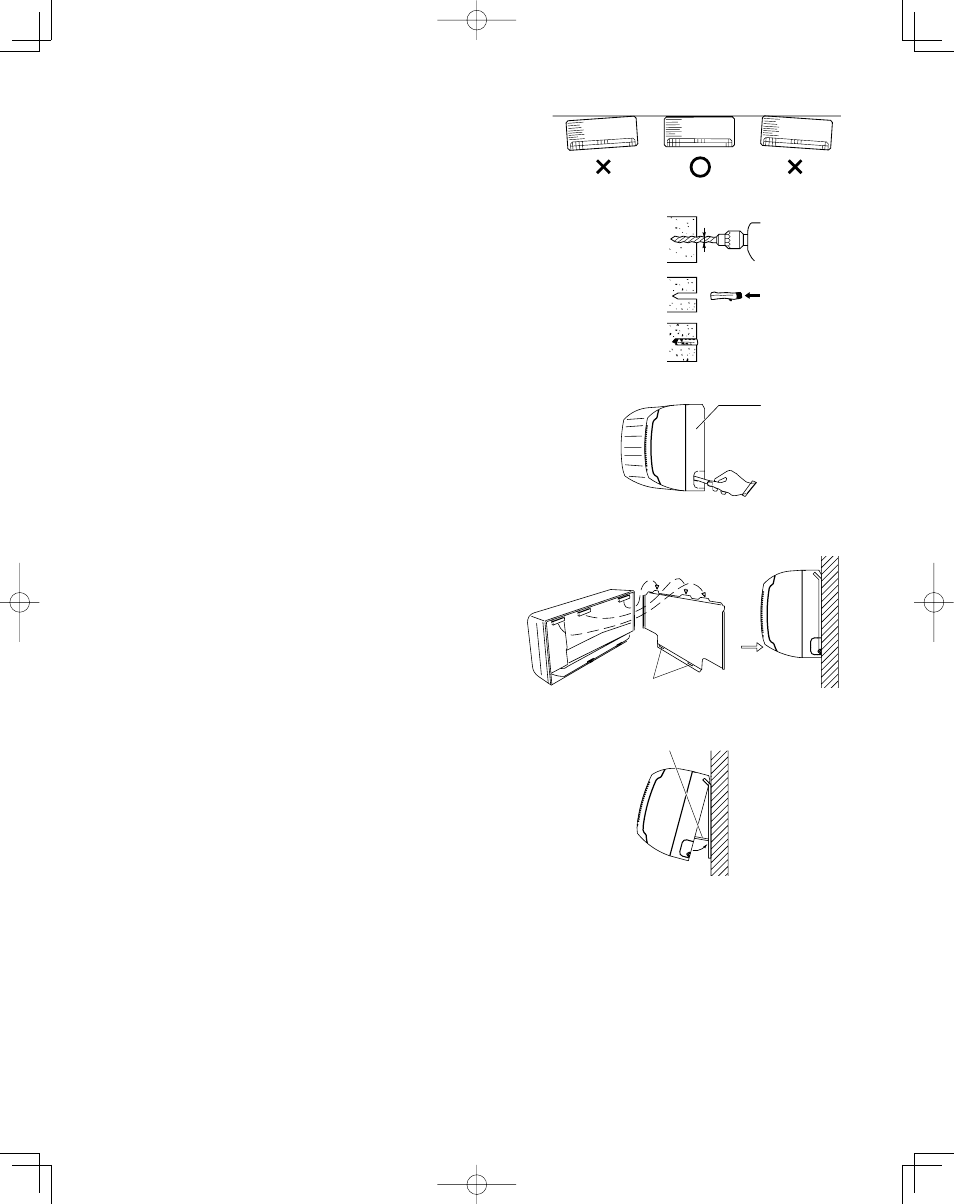
(2) Check with a tape measure or carpenter’s level. This is
important so that the unit is correctly installed. (Fig. 3-42)
(3) Make sure the panel is flush against the wall. Any space
between the wall and unit will cause noise and vibration.
b) If the Wall is Brick, Concrete or Similar
Drill 3/16" dia. holes in the wall. Insert Rawl plugs for
appropriate mounting screws. (Fig. 3-43)
3-19. Removing the Grille to Install the Indoor Unit
In principle, with this model wiring can be completed without
removing the grille.
However, if it is necessary to change the settings on the PCB.
3-20. Preparing the Tubing
(1) Arrangement of tubing by directions
a) Right or left tubing
The corner of the right or left frame should be cut with a
hack saw or similar. (Fig. 3-44)
b) Right-rear or left-rear tubing
In this case, the corners of the frame do not need to be
cut.
(2) Be sure to insulate the part of the drain hose that is run
indoors, and the refrigerant tubing.
If these are not insulated, condensation may result in dripping
and damage to walls and furniture.
The flare nuts on the 24-type (only) are large;
therefore, use the supplied insulation material.
(3) To mount the indoor unit on the rear panel.
1. When installing the indoor unit, position the indoor unit
onto the installation tabs on the upper part of the rear
panel. (Fig. 3-45)
2. Press on the air outlet to hold it in place, and press the
lower part of the indoor unit until a “click” sound is heard
and the indoor unit is securely fastened to the installation
tabs on the lower side of the rear panel. (Fig. 3-46)
Raising the clamp to lift up the indoor unit will facilitate this
work. (Fig. 3-47)
To remove the indoor unit, press up on the 2 locations
(
▲
▲
marks) on the lower part of the unit frame to disconnect
the installation tabs. Refer to Section 3-16. “Removing the
Rear Panel from the Unit” (Fig. 3-35).
Then lift up the indoor unit to remove it.
Fig. 3-42
Fig. 3-43
3/16"
dia. hole
Rawl plug
Frame
Right tubing
outlet
When left and right side tubing
Fig. 3-44
Fig. 3-46
Press
Fig. 3-47
Clamp
Fig. 3-45
Installation tabs
Installation tabs