P077, P078, P079 – Siemens G85139 User Manual
Page 29: P081, P082, P083, P084, P085, P089, P091
5. SYSTEM PARAMETERS
English
Parameter
Function
Range
[Default]
Description / Notes
© Siemens plc 1997
G85139-H1750-U049-B
29
26/09/97
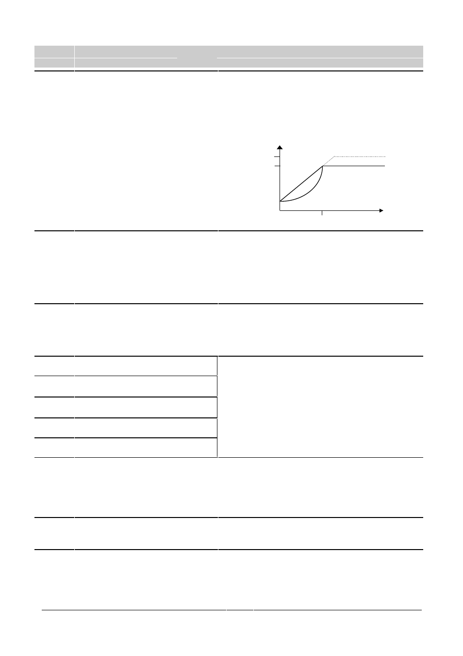
P077
Control mode
0 - 2
[1]
Controls the relationship between the speed of the motor and the
voltage supplied by the inverter. One of two modes can be selected:
0/1 = Linear voltage/frequency
Use this curve for synchronous motors or motors
connected in parallel.
2 =
Quadratic voltage/frequency relationship
This is suitable for centrifugal pumps and fans.
P078
•
Continuous boost (%)
0 - 250
[100]
Operates continuously over the whole frequency range.
For many applications it is necessary to increase low frequency torque.
This parameter sets the start-up voltage at 0 Hz to adjust the available
torque for low frequency operation. 100% setting will produce rated
motor current at low frequencies.
WARNING:
If P078 is set too high, overheating of the motor
and/or an overcurrent trip (F002) can occur.
P079
•
Starting boost (%)
0 - 250
[0]
For drives which require a high initial starting torque, it is possible to
set an additional current (added to the setting in P078) during ramping.
This is only effective during initial start up and until the frequency
setpoint is reached.
Note:
This increase is in addition to P078.
P081
Nominal frequency for motor (Hz)
0 - 400.00
[50.00]
P082
Nominal speed for motor (RPM)
0 - 9999
[
] These parameters must be set for the motor used.
P083
Nominal current for motor (A)
0.1 - 99.9
[
]
Read the specifications on the motor’s rating plate (see Figure 10 in
section 3.2.1).
P084
Nominal voltage for motor (V)
0 - 1000
[
]
Note: The inverter’s default setting vary according to the power rating.
P085
Nominal power for motor (kW/hp)
0 - 100.0
[
]
P089
•
Stator resistance (
Ω
)
0.01-100.00
[
]
The stator resistance of the motor should be entered in this parameter.
The value entered should be the resistance between any two phases
with the motor connected. The measurement should be made at the
inverter output terminals with power off.
Note:
If the value of P089 is too high then an overcurrent trip
(F002) may occur.
P091
•
Serial link slave address
0 - 30
[0]
Up to 31 inverters can be connected via the serial link and controlled
by a computer or PLC using the USS protocol. This parameter sets a
unique address for the inverter.
V
N
(P084)
f
N
(P081)
V
N
f
0/1
2
V
max