Sierra Monitor Corporation 5100-06-IT User Manual
Page 48
Model 5100-XX-IT Toxic Gas Sensor Module
Page: 44
8.7
APPENDIX G1: 5100-25-IT GAS SENSOR MODULE
1. Calibration of 5100-25-IT (Supplement to Instructions in Section 6)
2. Equipment Required
The following tools and equipment will be required for calibration:
-
Permeation Device Calibrator (Model 9210-00), with
Ammonia Permeation Tube (Model 9211-09).
-
Calibration Adapter (Model 5358-01)
3. Permeation Device Calibrator Operation
The calibrator is a portable device with a pump that operates from a
1.5 V alkaline size D battery. A fresh battery should allow 8 hours of
continuous operation. The permeation device will probably be
shipped separately, usually in a pipe with screw cap ends, one of
which will be marked for opening. The permeation device should
come fitted with a scrubber, but, as a precaution, open the pipe and
remove the permeation device in a well ventilated area.
1. Remove the scrubber from the permeation device and attach the
device to the stainless steel “Tee” assembly inside the calibrator
box. Tighten the connection with a wrench, with the device
resting inside one of the openings in the rack.
2. Close the door of the calibrator and turn on the pump switch.
3. Set the flow rate for the desired ppm of ammonia. The desired
flow rate for calibration of the Model 5100-25-IT is 300-500
cc/min. and the concentration range should be set between the
high alarm point and 100 ppm full scale.
The carrier gas flow rate can be calculated from the formula:
P = (CxF)/K
Where P = the permeation rate in nanograms/min., and C = ppm of span gas, F = carrier gas flow rate in
ml./min. and K = 1.437 for ammonia. The permeation rate for the temperature read on the front of the
calibrator can be obtained from permeation rate vs. temperature chart.
4. Run the gas calibrator for 30 min. before attaching the output hose to the ammonia sensor.
5. When the use of the calibrator is completed, do not turn off the pump unit until the permeation device
has been removed from the “Tee” and the gas scrubber reattached. Failure to remove the permeation
device when the pump has been turned off will contaminate the system with high amounts of the
permeating gas and result in erroneous concentrations. The device, with scrubber, can be stored in the
storage rack overnight, but should not stay in the gas calibrator for longer storage periods.
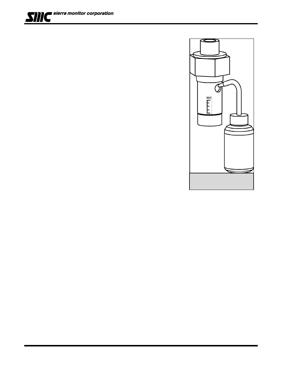
4. Sensor Assy. Rebuild Procedure
Follow procedures outlined in Electrolyte/Membrane Replacement (See Fig. 8-5)
The electrolyte needs to be replaced at least every six months, or if there is evidence of low sensor
output. The membrane and O-Ring should be replaced at the same time that the electrolyte is
replaced.
5. Equipment Required
- Electrolyte Recharge Kit (SPX27057 for Model 5100-25-IT and SPX27061 for Model 5100-26-
IT) consisting of the electrolyte, package of 5 membranes, 5 0-Rings and alcohol wipes to clean
the electrode.
- Tweezers to aid in removing and replacing the membrane
Figure 8 - 4: Module
Components