Sierra Monitor Corporation 5100-06-IT User Manual
Page 15
Model 5100-XX-IT Toxic Gas Sensor Module
Page: 11
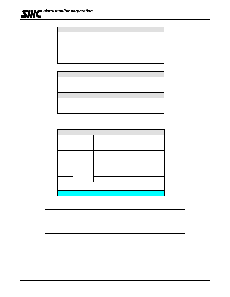
P2
PCB Label
Function
1
RS 485
+
RS 485 (+) (A)
2
-
RS 485 (-) (B)
3
S
RS 485 shield (Isolated GND)
4
RS 485
+
RS 485 (+) (A)
5
-
RS 485 (-) (B)
6
S
RS 485 shield (Isolated GND)
P3B
PCB Label
Function
1 P
VDC
Power
2
S
Sentry Signal or Communication
3 G
VDC
Ground
P3A
4 P
VDC
Power
5
S
Sentry Signal or Communication
6 G
VDC
Ground
P4 Connections are only available when the optional Relays are included
P4
PCB Label
Function
1
WARNING
N/C
Low Alarm Relay NC
2
COM
Low Alarm Relay COM
3
N/O
Low Alarm Relay NO
4
ALARM
N/C
High Alarm Relay NC
5
COM
High Alarm Relay COM
6
N/O
High Alarm Relay NO
7
TRBL
N/C
Trouble Alarm Relay NC *
8
COM
Trouble Alarm Relay COM*
9
N/O
Trouble Alarm Relay NO*
* Trouble relay is fail safe so it is energized for normal operation,
functions are labeled for normal operation.
8. Establish the module address according to section 4.5.
NOTES
The starting delay period normally takes approximately 3 minutes but under some
circumstances can take longer.
For optimum performance, it is recommended that a calibration be performed after 24 hours of
operation.