Sierra Monitor Corporation 5100-06-IT User Manual
Page 28
Model 5100-XX-IT Toxic Gas Sensor Module
Page: 24
6. CALIBRATION
6.1 CALIBRATION FREQUENCY
The Gas Sensor Module has been calibrated in the factory prior to shipment. It is recommended that the user
calibrate before placing into service. The sensor module must be calibrated every 180 days at a minimum.
Periodic functional tests are advisable for critical applications and hostile environments. Oxygen sensors will
require more frequent adjustment.
The sensor module microprocessor software includes high-level self-checking algorithms which provide
continuous sensor diagnostic and self-adjustment. Users may select to increase calibration frequencies based
on low-drift experience during first two calibration periods.
6.2 CALIBRATION PREPARATION
Calibration of the sensor is accomplished by simple menu based steps and application of span gas.
N
OTE
If an error is made during any stage of the calibration process, hold the magnet stick at the [M] for 10 seconds. A scrolling display
will indicate “calibration aborted” and the sensor module will exit the calibration activity and return to normal operating mode. The
calibration procedure can then be restarted.
Calibration must be performed only when the area is known to be clear of the gas of interest. When in doubt,
use a portable instrument to confirm that there is no background.
For compliance with Factory Mutual (FM) Approvals, the Sierra Monitor Model 1250-01, 1260 -05 and 1260-45
are the FM Approved calibration gas delivery devices. Use the Model 5358-01 Calibration Adapter delivery
fitting.
NOTE: Refer to Appendix G1 for information on use of permeation tube for 5100-
25-IT and Appendix G2 for 5100-26-IT calibration.
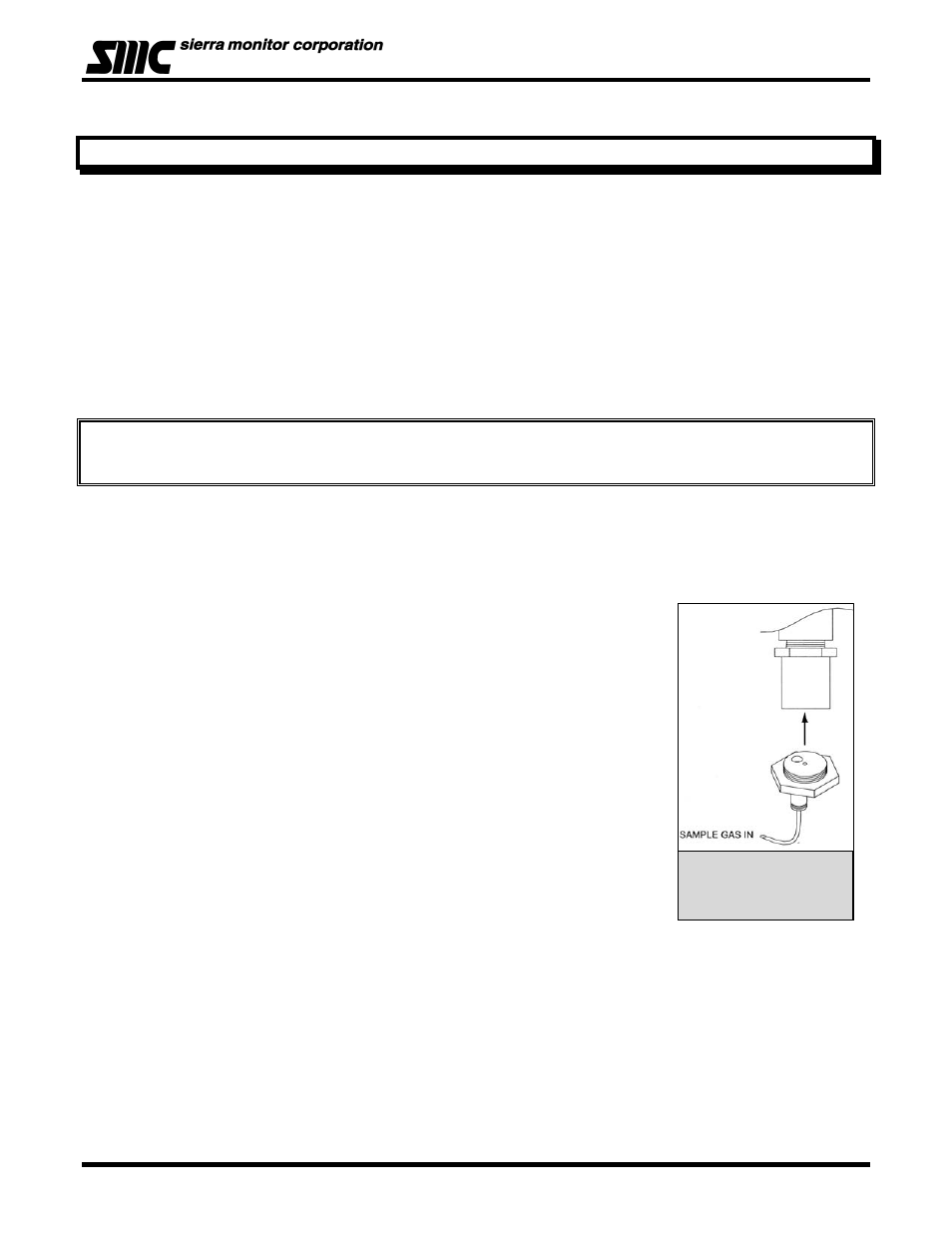
6.3 CALIBRATION GAS DELIVERY METHODS
Calibration gas can be delivered to the sensors via the Model 5358-01:
Calibration Adapter (Figure 6-1) - used with portable calibrators.
CALIBRATION PROCEDURE
The Calibration Menu is described on Table 6-1:
The procedure requires that the menu “keys” be activated using the magnet
stick.
Each key press steps through the process of setting the zero value for clean air
and then setting the span value.
At each of these steps, apply calibration gas of the value corresponding to the
setting accepted on the sensor module display.
6.4 SENSOR EXPOSURE TO GAS
Calibration gas must be delivered to the sensor using the flow rate and duration
listed in below:
Model Calibration
Gas
Flow
Period
5100-03-IT Air
300 cc of Zero Air or exposure to Ambient Air (3 minutes)
5100-04-IT Carbon Monoxide 300 cc/min
Until Stable (minimum 3 minutes)
5100-05-IT Hydrogen Sulfide 300 cc/min
Until Stable (minimum 3 minutes)
5100-06-IT Chlorine
300 cc/min
Until Stable (minimum 3 minutes)
5100-08-IT* Chlorine
300 cc/min
Until Stable (minimum 3 minutes)
5100-10-IT Sulfur Dioxide
300 cc/min
Until Stable (minimum 3 minutes)
5100-12-IT Nitrogen Dioxide
300 cc/min
Until Stable (minimum 3 minutes)
5100-21-IT Hydrogen Chloride 300 cc/min
5100-25-IT Ammonia
See Appendix G1
5100-26-IT Hydrogen Fluoride See Appendix G2
5100-88-IT* Carbon Dioxide
300 cc/min
Until Stable (minimum 3 minutes)
Figure 6 - 1: Model
5358-01 Calibration
Adapter