Installation – Sierra Monitor Corporation 5100-06-IT User Manual
Page 12
Model 5100-XX-IT Toxic Gas Sensor Module
Page: 8
4. INSTALLATION
4.1 SENSOR MODULE LOCATIONS
NOTE
All
IT
modules are factory pre-configured and calibrated.
All modules are tagged to indicate the configuration including the sensor module number
Identify all components during unpacking and install using the factory configuration.
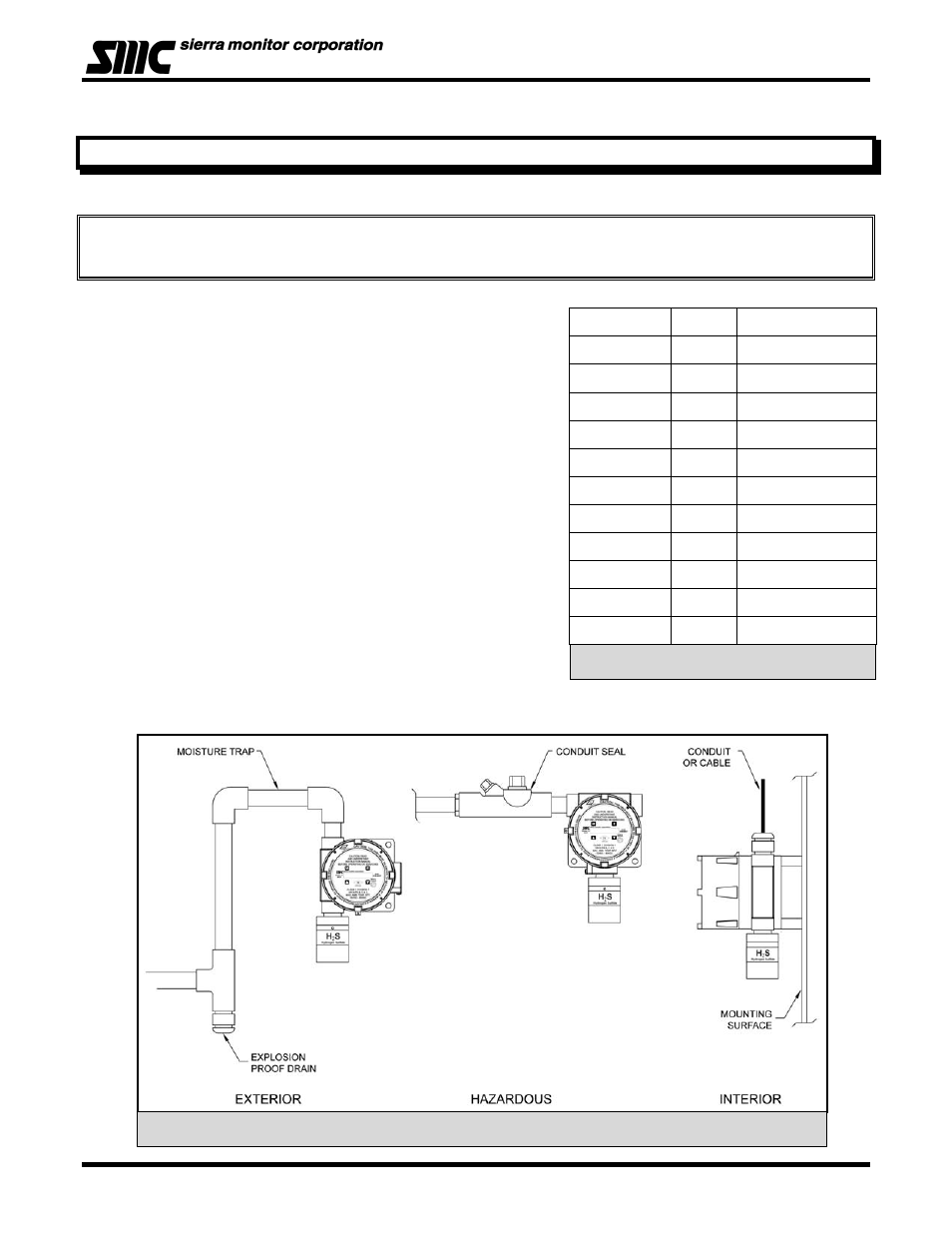
The gas sensor module utilizes a diffusion type sensor which
should be located close to either the expected source or
destination of the gas hazard. If the gas is heavier than air, the
sensor module should be installed within 24 inches of the ground
or floor. If it is lighter than air, move it above 6’.
After optimum locations are determined based on the above
recommendations, consideration should be given to placing the
sensor modules in locations which are accessible for calibration
service. Slight adjustments to the location of the sensor module
may have little impact on effectiveness but major effect on
accessibility.
• Modules should be placed close to the potential source
of gas.
• Modules should be placed in areas accessible for
calibration.
• Sensors should be pointed down and the conduit
should include an inverse trap to reduce moisture
(condensation) from accumulating in the electronics
enclosure.
• Remote calibration fitting (5360-00) should be used to
facilitate calibration gas delivery. Run polyurethane tubing (1/4” O.D. x 1/8” I.D.) from fitting to an
accessible location.
Model Gas Gas
Density
N/A Air 1.00
5100-04-IT CO
0.97
5100-05-IT H
2
S 1.19
5100-06-IT Cl
2
2.49
5100-08-IT ClO
2
3.09
5100-10-IT SO
2
2.26
5100-12-IT NO
2
2.12
5100-21-IT HCl
1.27
5100-25-IT NH
3
0.60
5100-26-IT HF
1.86
5100-88-IT CO
2
1.53
Table 4 - 1: Specific Graities
Figure 4 - 1: Typical Mounting Options