Installation – JVC KA-HD250 User Manual
Page 6
PREPARATIONS
10
Installation
Mounting on a Tripod
Use the screw holes on the bottom to mount on a tripod.
There are multiple screw holes. Use well-balanced holes to
mount to a tripod.
Mounting the Camera
Prepare the camera as follows before mounting.
• Attach the lens.
• Attach the microphone.
• Remove the viewfinder.
For details, refer to GY-HD250’s INSTRUCTION MANUAL.
1.
Open the side cover.
2.
While pushing the safety lever, pull the lock lever toward
the front until the front mount clip clicks into place.
3.
Place the camera on this device and align the rear base
mount of the camera with the pin on this device.
4.
Hold the camera on the top and slide forward so that the
base mount of the camera is locked by the front mount
clip of this device as it clicks into place.
CAUTION
• The front base mount may lock even when the pin on this
device and the rear base mount attachment hole on the
camera is not attached. After attaching, confirm that the
camera has been firmly attached. The camera may fall
and cause injury or accident if it is not attached properly.
• When transporting with the camera attached to this
device, hold the bottom of this device. If transported with
the camera handle, the attachment may come off and
this device may fall and cause injury or accident.
Screw
holes
Safety lever
Lock lever
Pin
Front
mount
clip
Rear base mount
Front base mount
11
Eng
lis
h
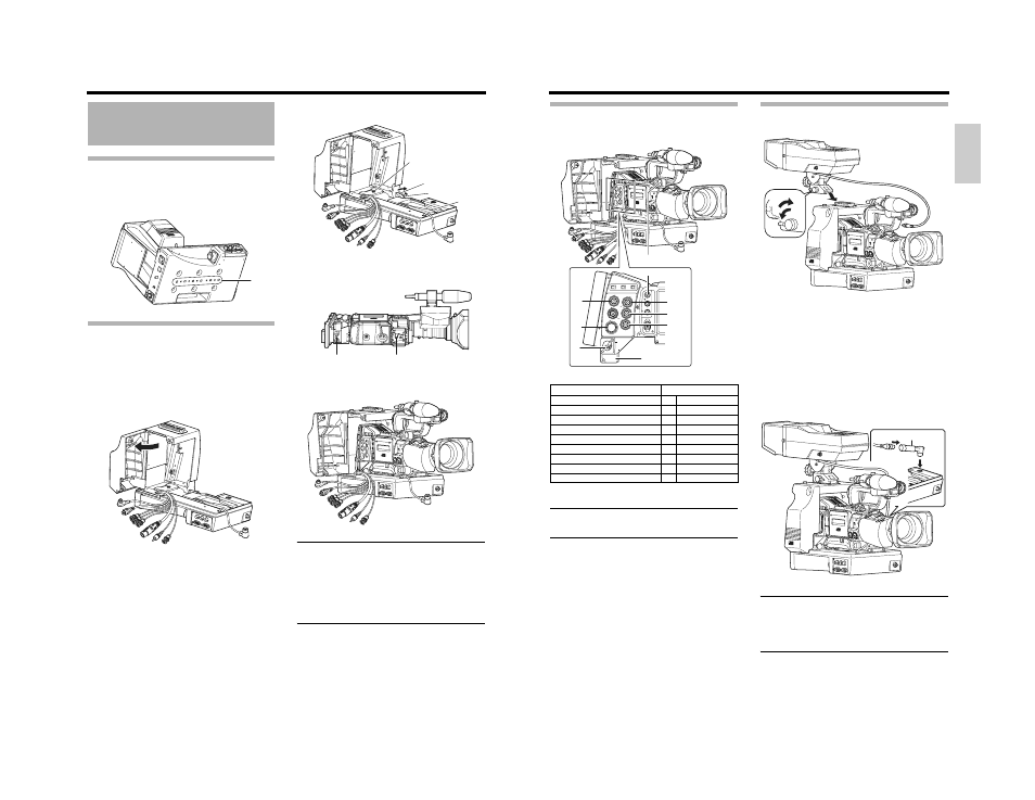
Connecting Cables
Connect the cables for this device to the camera.
Connect the cable for this device to the camera terminal.
MEMO
• Turn off the device before connecting cables.
• Do not touch the plug terminals when connecting.
• Insert the DC cable plug all the way in until it locks.
Connecting the Viewfinder (VF-P400)
1.
Loosen the lock lever.
Turn the viewfinder lock lever counterclockwise and
loosen the lock lever.
2.
Attach the viewfinder.
Slide the viewfinder forward along the viewfinder holder
guides on the top of this device.
3.
Tighten with the lock lever.
Turn the viewfinder lock lever clockwise and tighten the
lock lever.
4.
Connect the cables.
Connect the viewfinder cable and conversion plug (KA-
V400) and connect the conversion plug to the viewfinder
output terminal (20 pin) of this device.
MEMO
• Do not connect a monitor to the VF OUTPUT (Y/P
B
/P
R
/
RGB) terminal on the side of this device. When monitors
are simultaneously connected to two VF OUTPUT termi-
nals, signals are not properly output.
• Do not connect anything other than the specified view-
finder to the viewfinder output terminal (20 pins).
Cable (type)
Camera
terminal
GENLOCK
(BNC)
1
GENLOCK
REMOTE
(Round 6-pin)
2
REMOTE
DC OUTPUT
(XLR 4-pin)
3
DC INPUT
VIDEO
(RCA)
4
VIDEO
Y
(BNC)
5
Y
P
B
(BNC)
6
P
B
P
R
(BNC)
7
P
R
STUDIO
(Round 10-pin)
8
STUDIO
VF
(Round 20-pin)
9
VF
DC INPUT
REMOTE
HD/SD
GENLOCK/AUX IN
P
TC OUT
IEEE 1394
CH2-AUDIO OUT
-CH1 VIDEO
STUDIO
P
TC IN
Y
SDI
9
4
5
6
7
8
1
2
3
2.
1.
3.
4.
4.
Plug