On off min max push – JVC KA-HD250 User Manual
Page 5
8
INTRODUCTION
Controls, Indicators and Connec-
tors (Cont’d)
Rear Section
g
[TALLY] TALLY Lamp
Lights up green when in stand-by (preview). Lights up red
when the camera image is selected with the remote con-
troller.
h
[INTERCOM] Intercom Input Terminal (XLR 5 Pin)
Input terminal for intercom headset. (Dynamic only)
Recommended headset: DT109 (Beyerdynamic)
i
[INTERCOM MIC] Intercom Mic [ON/OFF] Switch
[ON/OFF] switch for intercom headset microphone. Set to
[ON] to use the headset microphone.
j
[INTERCOM LEVEL] Intercom Receiver Volume
Use for adjusting the intercom headset receiver volume
level.
k
[CALL] CALL button/Power indicator
Lights green when the studio adapter is turned on.
However, lights up amber when the camera is off.
Press to send call signal to the remote control unit opera-
tor if intercom headset is not in-use.
Button indicator changes from green to red when the but-
ton is pressed.
When this button is pressed and held down, call signal is
sent to the remote control unit and the [TALLY] indicator
blinks. Once the [CALL] button is released, call signal is
no longer sent and the [TALLY] indicator of the remote
control unit turns off.
l
[DC INPUT] DC Power Input Terminal (XLR 4 Pin)
Connect DC power to this terminal if Remote Control Unit
RM-P210 is not connected. For DC power supply, use the
IDX IA-60a or VL-2PLUS.
CAUTION
When cable is connected to the DC INPUT terminal while
supplying power from the RM-P210, power will be inter-
rupted.
Turn off connected devices when connecting a cable to the
DC INPUT terminal.
Bottom Section
m
Screw Holes for Mounting Tripod
Signal
1
MIC (H)
2
MIC (C)
3
EAR (C)
4
EAR (H) – LEFT
5
EAR (H) – RIGHT
INTERCOM
INTERCOM MIC
INTERCOM LEVEL
CALL
DC INPUT
ON
OFF
MIN
MAX
PUSH
h
i
j
k
l
g
1
3
2
5
4
(Surface profile)
m
9
Eng
lis
h
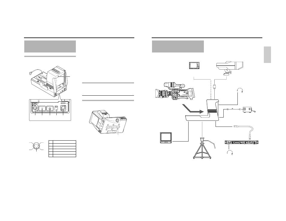
PREPARATIONS
Basic System
z Power is supplied by the Remote Control Unit RM-P210 via the 26 pin camera cable when in-use. If the Remote Control Unit
RM-P210 is not in-use, use AC power adapter.
MACRO
USER 3
USER 2
USER 1
STATUS
MENU
2
1
ND FILTER
REC
OFF
ON
POWER
WHT.BAL
AUTO
AUDIO
LEVEL
AUTO
CH-1
CH-2
VF BRIGHT
CALL
TALLY
INTERCOM
LEVEL
FULL AUTO
F1
SHUTTER
GAIN
F2
F3
MENU/SHUTTER
GAIN
PAINT
AUTO
B
R
W.BAL
AUTO
MANU
WHITE
MASTER BLACK
POWER
I
O
IRIS
STEP
SHUTTER
MENU
PUSH-ON
DOWN
UP
VARIABLE
PUSH-ON
HIGH
LOW
B
A
PRESET
CLOSE
OPEN
MID
DOWN
UP
F4
BARS
REMOTE CONTROL UNIT RM-P210
View Finder
DM-3106 (Astrodesign)
V-R70P-HAD (Marshall Electronics)
HD CAMERA RECORDER
GY-HD250/GY-HD251
PROMPTER OUTPUT
terminal
Monitor
Dolly
Headset
DT109 (Beyerdynamic)
Headset
DT109 (Beyerdynamic)
Remote Control Unit
RM-P210
REMOTE cable
RM terminal
Tripod
DC INPUT terminal
DC cable
AC Power Adapter
IA-60a, VL-2PLUS (IDX)
Conversion plug
STUDIO KIT
KA-HD250
VF OUTPUT
terminal
(BNC × 3)
VF OUTPUT
terminal
(Round 20-Pin)
View Finder
VF-P400
INTERCOM terminal