Power supply leds and self-test button, Fan tray – Juniper Networks M5 User Manual
Page 39
Fan Tray
Description
Specification
Input DC current rating
13.5 A @ –48 V
Output voltages
+1.5 V, +2.5 V, +3.3 V, +5.0 V, +12 V, +12 V
The DC power supplies are marked –48 VDC. This is the nominal voltage
associated with the battery circuit. Any higher voltages are to be associated
only with float voltages for the charging function.
Power Supply LEDs and Self-test Button
Table 7 describes the LED on both AC and DC power supplies.
Table 7: States for Power Supply LED
Label
Color
State
Description
On steadily
Power supply is functioning normally, input is
occurring, outputs are within range, and the
temperature is within range.
OUTPUT
OK
Blue
Blinking
Power supply has failed.
The self-test button on the power supply faceplate initiates a self-test sequence. Do not press
this button; it is for use by qualified service personnel only.
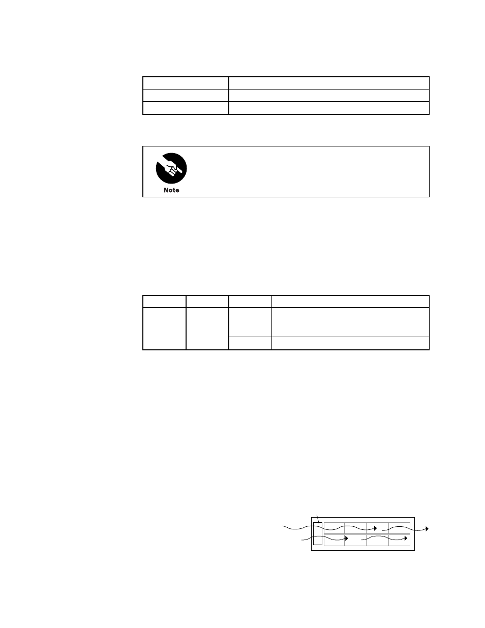
Fan Tray
The router cooling system consists of a fan tray that installs into the chassis from the rear, as
shown in Figure 3. It houses four fans, which draw room air into the chassis to keep the
internal temperature below a maximum acceptable level. The air flows side-to-side in the
chassis, as shown in Figure 10.
Figure 10: Airflow through the Chassis
1305
Front of chassis
Fan tray
Hardware Component Overview
19