Replace connector, Replace routing engine components – Juniper Networks M5 User Manual
Page 138
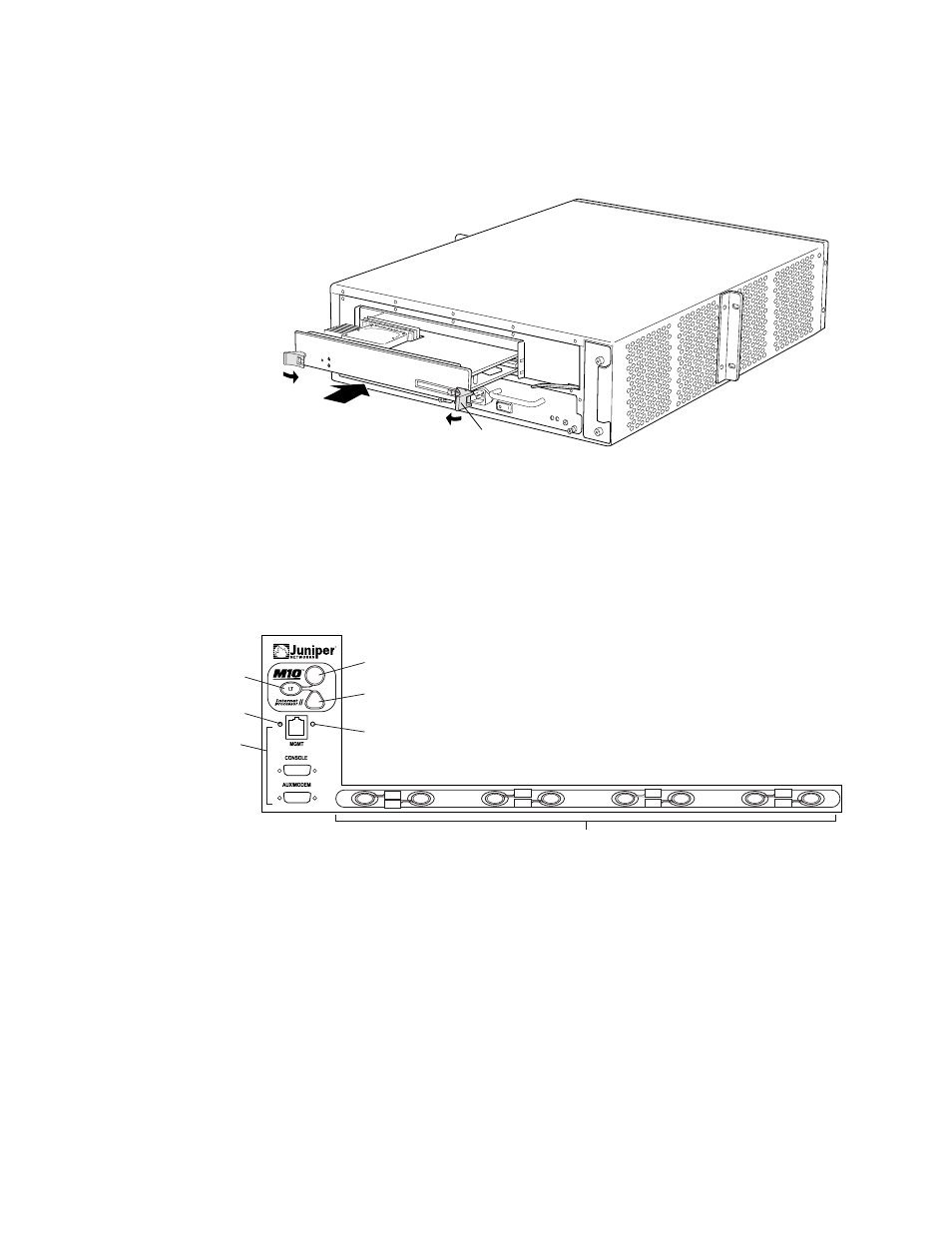
Replace Routing Engine Components
Figure 43: Install the Routing Engine
1313
Extractor
clip
Replace Connectors to Routing Engine Interface Ports
The ports on the craft interface connect the Routing Engine to external management
devices (see Figure 44).
Figure 44: Routing Engine Interface Ports and Alarm Relay Contacts
R
1336
Red alarm LED
Lamp test button
Routing Engine
ports
PIC online/offline buttons
Yellow alarm LED
Link status LED
Activity status LED
PIC0/3
PIC1/3
PIC0/2
PIC1/2
PIC0/1
PIC1/1
PIC0/0
PIC1/0
To replace the cables that connect to the ports, perform the procedures described in the
following sections:
•
Replace the Management Ethernet Cable on page 118
•
Replace the Console or Auxiliary Cable on page 119
Replace the Management Ethernet Cable
To connect the Routing Engine to a network for out-of-band management, connect an
Ethernet cable with RJ-45/RJ-45 connectors to the MGMT port on the craft interface. One
118
M5 and M10 Internet Routers Hardware Guide