Intel 430TX User Manual
Page 15
15
8MB * 32 DS
X
64MB
8MB * 32 DS
1MB * 32 SS
72MB
8MB * 32 DS
2MB * 32 DS
80MB
8MB * 32 DS
4MB * 32 SS
96MB
8MB * 32 DS
8MB * 32 DS
128MB
16MB * 32SS
X
128MB
16MB * 32SS
16MB * 32SS
256MB
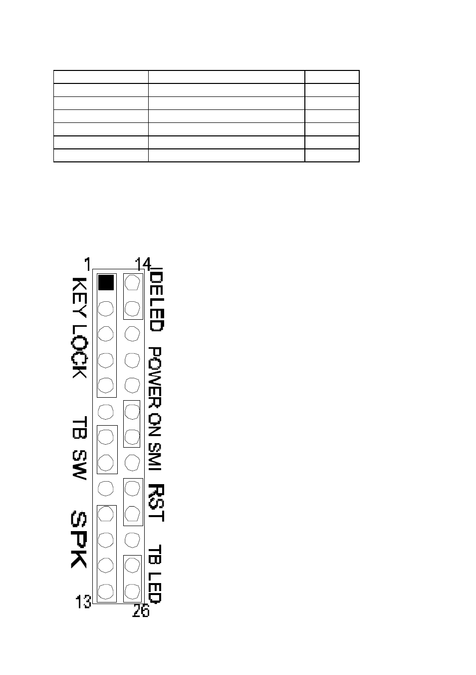
1.5 Install IDE, Enhanced I/O and Front Panel Connectors
There is a special design that CN9 is for Key Lock, Sleep/Resume SW,
Speaker, IDE LED, TB SW, Reset SW, and Turbo LED. It is
convenient for you to connect the cable from front board of Case.
CN9: 1-5,
Key Lock - Keyboard lock switch
& power LED connector. 1. Power LED (+),
2. N/C, 3. GND, 4. Key lock, 5. GND
CN9: 7-8,
Turbo Switch.
CN9: 10-13,
Speaker - Connect to the
system's speaker for beeping. 10. Speaker, 11.
GND, 12. GND, 13. VCC.
CN9: 14-15
, IDE LED Indicator - LED ON
when on board PCI IDE HDD activities.
C
N9: 19-20
, Turn on power when ATX power
supply is on sleep mode
CN9: 22-23,
Reset - Short to restart system.
CN9: 25-26,
Turbo LED Indicator - LED ON
when high speed (CN9: 7-8 SHORT).
- 41210 (64 pages)
- 8xC251TQ (20 pages)
- ENTERPRISE PRINTING SYSTEM (EPS) 4127 (84 pages)
- U3-1L (20 pages)
- 80960HA (104 pages)
- X58 (54 pages)
- ESM-2850 2047285001R (91 pages)
- ATOM US15W (54 pages)
- D915GVWB (4 pages)
- XP-P5CM-GL (28 pages)
- AX965Q (81 pages)
- CORETM 2 DUO MOBILE 320028-001 (42 pages)
- CV700A (63 pages)
- 80C188EA (50 pages)
- X25-M (28 pages)
- XP-P5IM800GV (26 pages)
- IB868 (60 pages)
- D865GVHZ (88 pages)
- IB865 (64 pages)
- Altera P0424-ND (1 page)
- 8086-2 (30 pages)
- IXDP465 (22 pages)
- IWILL P4D (104 pages)
- GA-8I955X PRO (88 pages)
- FSB400 (PC2100) (96 pages)
- D845GLAD (4 pages)
- NAR-3041 (1 page)
- 87C196CA (136 pages)
- G52-M6734XD (74 pages)
- A96134-002 (10 pages)
- Express Routers 9000 (8 pages)
- 82540EP (45 pages)
- D865GLC (94 pages)
- IB850 (69 pages)
- MB898RF (62 pages)
- Arima LH500 (78 pages)
- V09 (33 pages)
- I/O Processor (22 pages)
- M600 (110 pages)
- SE7520JR2 (63 pages)
- SERVER BOARD S5520HCT (30 pages)
- Extensible Firmware Interface (1084 pages)
- GA-8IPXDR-E (70 pages)
- D845EBG2 (4 pages)
- AW8D (80 pages)