7 the mcm, Capacitors, Chapter 2. system structure and design – IBM 990 User Manual
Page 47: Figure 2-10 mcm card
Chapter 2. System structure and design
35
– High Speed Token Ring
PCI Cryptographic Accelerator (PCICA, two processors per feature).
PCIX Cryptographic Coprocessor (PCIXCC, one processor per feature).
The STI-2 card provides two output ports to support the ICB-2 links. The STI-3 card
converts the output into two 333 MBps links
The STI-3 card provides two output ports to support the ICB-3 links. The STI-3 card
converts the output into two 1GBps links.
The ICB-4 channels are unique to the z990. They do not require a slot in the I/O cage and
attach directly to the STI of the communicating CPC with a bandwidth of 2.0 GBps.
2.1.7 The MCM
The z990 MultiChip Module (MCM) contains 16 chips: eight are processor chips (12 PUs),
four are System Data cache (SD) chips, one is the Storage Control (SC) chip, two chips carry
the Memory Subsystem Control function (MSC), and there is one chip for the clock
(CLK-ETR) function.
The 93 x 93 mm glass ceramic substrate on which these 16 chips are mounted has 101
layers of glass ceramic with 400 meters of internal wiring. The total number of transistors on
all chips amounts to more than 3.2 billion.
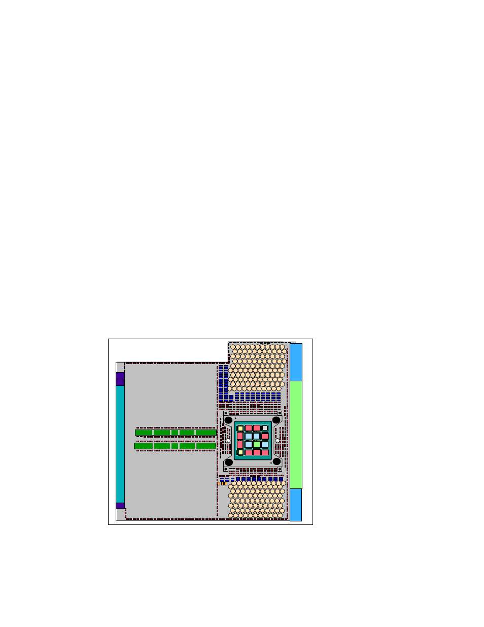
The MCM plugs into a card that is part of the book packaging, as shown in Figure 2-10. The
book itself is plugged into the CEC board to provide interconnectivity between the books, so
that a multibook system appears as a Symmetric Multi Processor (SMP). The MCM is
connected to its environment by 5184 Land Grid Arrays (LGA) connectors. Figure 2-11 on
page 36 shows the chip locations.
Figure 2-10 MCM card
c
o
nn
ec
to
r:
c
a
c
h
e
r
ing
/
c
n
tl
po
w
e
r
po
w
e
r
capacitors
capacitors
MC1
MC0
PU1
CLK
PU2
SD1
SD0
PU0
SD2
SC0
SD3
PU5
PU6
PU7
PU3
PU4