Figure 1. thermal design process, 2 definition of terms, Table 1. definition of terms (sheet 1 of 2) – Intel CORETM 2 DUO MOBILE 320028-001 User Manual
Page 7: Definition of terms, Thermal design process
Core™ 2 Duo Mobile Processors—Introduction
Intel® Core™ 2 Duo Mobile Processors on 45-nm process-Thermal Design Guide
TDG
June 2008
7
Order Number: 320028-001
1.2
Definition of Terms
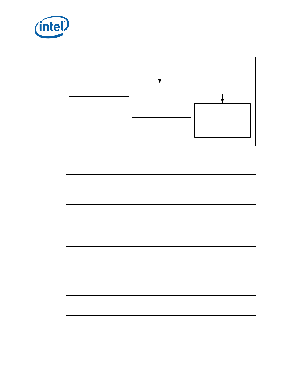
Figure 1.
Thermal Design Process
Table 1.
Definition of Terms (Sheet 1 of 2)
Term
Definition
FCPGA
Flip Chip Pin Grid Array. A pin grid array packaging technology where the die is
exposed on the package substrate.
FCBGA
Flip Chip Ball Grid Array. A ball grid array packaging technology where the die is
exposed on the package substrate.
T
JUNCTION-MAX
Maximum allowed component (junction) temperature. Also referred to as T
J-MAX
TDP
Thermal Design Power. Thermal solutions should be designed to dissipate this
target power level.
T
LA
Local ambient temperature. This is the temperature measured inside the chassis,
approximately 1 inch upstream of a component heatsink. Also referred to as T
A
.
Ψ
JA
Junction-to-ambient thermal characterization parameter. A measure of heatsink
thermal performance using the total package power. Defined as (T
JUNCTION
– T
LA
) /
Total Package Power
Ψ
TIM
Thermal interface material thermal characterization parameter. A measure of
thermal interface material performance using total package power. Defined as (T
CASE
– T
JUNCTION
)/ Total Package Power. Also referred to as Ψ
JS.
Ψ
SA
Sink-to-ambient thermal characterization parameter. A measure of heatsink
thermal performance using total package power. Defined as (T
SINK
– T
JUNCTION
)/
Total Package Power.
°C
Degrees in Celsius
CFM
Volumetric airflow rate in cubic feet per minute
in.
Inches
LFM
Airflow velocity in linear feet per minute
PCB
Printed circuit board
T
SINK
Heatsink temperature measured on the underside of the heatsink base.
• Package Level Thermal Models
• Thermal Model User’s Guide
Step 1: Thermal Simulation
• Reference Heatsinks
• Reference Mounting Hardware
• Vendor Contacts
Step 2: Heatsink Design
and Selection
Step 3: Thermal Validation
• Thermal Testing Software
• Thermal Test Vehicle
• User Guides