Core™2 duo, Processor, Atsink – Intel CORETM 2 DUO MOBILE 320028-001 User Manual
Page 16: Figure 5
Intel® Core™ 2 Duo Mobile Processors on 45-nm process for Embedded Applications
June 2008
TDG
Order Number: 320028-001
16
Thermal Solution Requirements—Core™ 2 Duo Mobile Processors
5.1.1
Calculating the Required Thermal Performance for the Intel
®
Core™2 Duo processor
Overall thermal performance, Ψ
JA,
is then defined using the thermal characterization parameter:
• Define a target component temperature T
JUNCTION
and corresponding TDP.
• Define a target local ambient temperature, T
A
.
The following provides an illustration of how to determine the appropriate performance targets.
Assume:
• TDP = 35 W and T
JUNCTION
= 105 °C
• Local processor ambient temperature, T
A
= 40 °C.
Using
Equation 1
, the maximum allowable resistance, junction-to-ambient, is calculated as:
To determine the required heatsink performance, a heatsink solution provider would need to
determine Ψ
CA
performance for the selected TIM and mechanical load configuration. If the heatsink
solution were designed to work with a TIM material performing at Ψ
TIM
≤ 0.50 °C/W, solving from
, the performance of the heatsink required is:
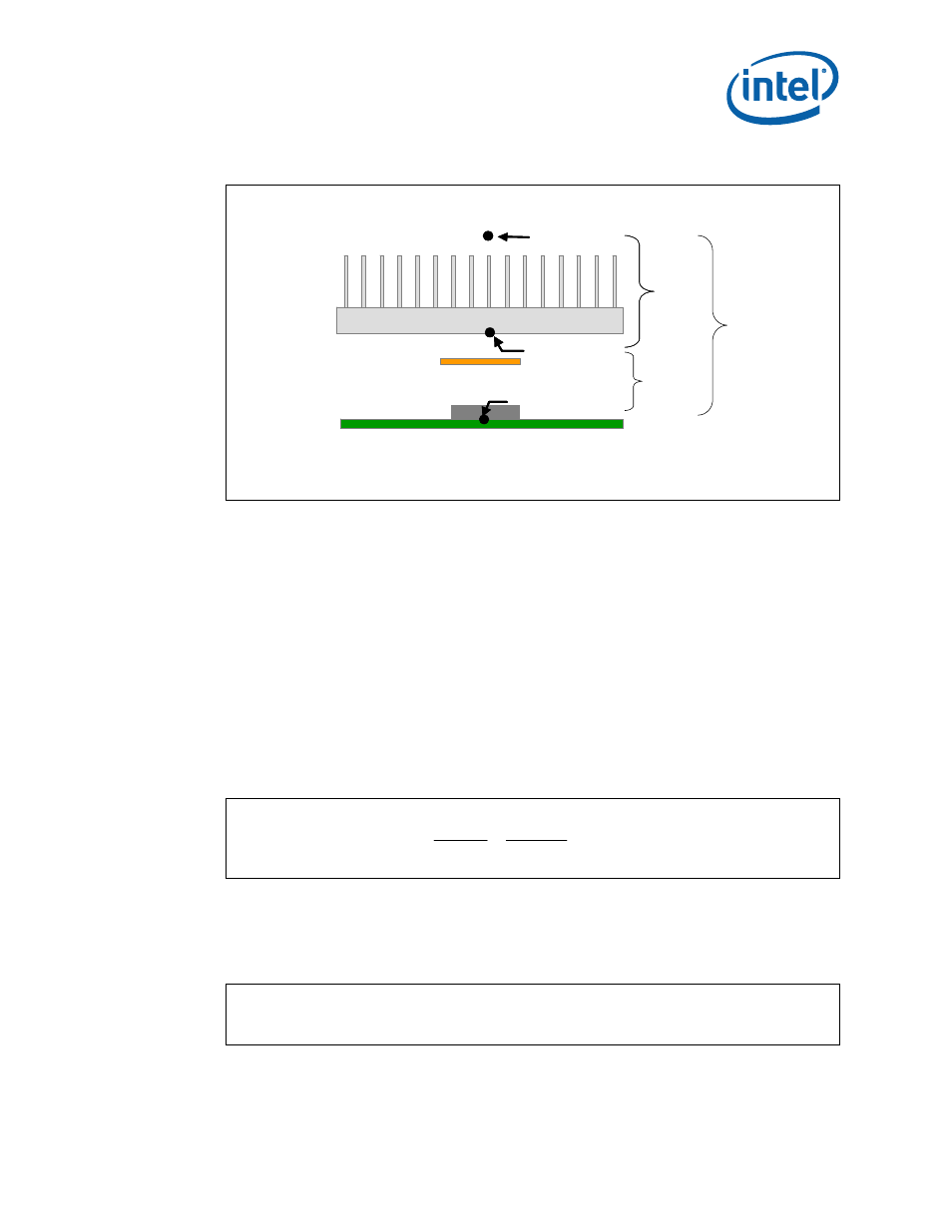
Figure 5.
Processor Thermal Characterization Parameter Relationships
Equation 3. Maximum Allowable Resistance
Equation 4. Required Performance of the Heatsink
T
S
T
J
T
A
Ψ
SA
Ψ
Ψ
TIM
Device
T
S
T
A
Ψ
SA
Ψ
TIM
Ψ
JA
HEATSINK
W
C
TDP
T
T
o
A
J
JA
/
857
.
1
35
40
105
=
−
=
−
=
Ψ
W
C
o
JS
JA
SA
/
36
.
1
50
.
0
86
.
1
=
−
=
Ψ
−
Ψ
=
Ψ