1 keep out zone requirements, 2 thermal performance, 6 heatsink fastener assembly – Intel CORETM 2 DUO MOBILE 320028-001 User Manual
Page 22: 7 thermal interface material (tim), Keep out zone requirements, Thermal performance, Heatsink fastener assembly, Thermal interface material (tim), Pcb as described in, Section 6.6, “heatsink
Intel® Core™ 2 Duo Mobile Processors on 45-nm process for Embedded Applications
June 2008
TDG
Order Number: 320028-001
22
Reference Thermal Solutions—Core™ 2 Duo Mobile Processors
6.5.1
Keep Out Zone Requirements
The keep out zone requirements on the PCB to use this heatsink are detailed in
Because it extends beyond the footprint of the device, it is critical for board
designers to allocate space for the heatsink.
6.5.2
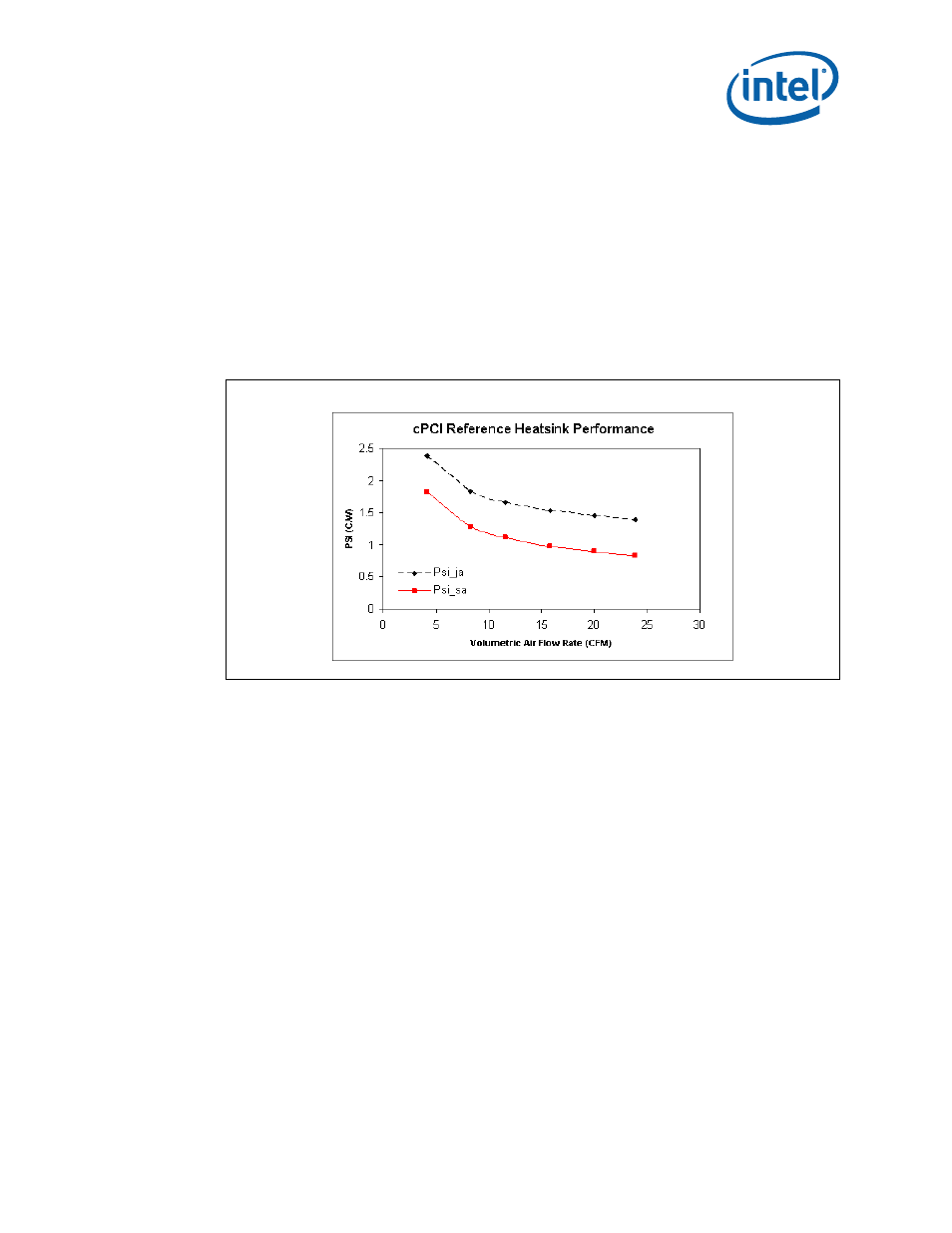
Thermal Performance
The cPCI reference heatsink is an all copper (C1100) design, intended for applications where vertical
space is limited. The heatsink has been tested at flow rates from 4 CFM to 24 CFM. For a 40 °C
external ambient and 17W TDP, the heatsink is expected to meet the thermal performance needed
when the air flow rate is at least 4 CFM.
6.6
Heatsink Fastener Assembly
The reference solutions use a screw, spring, and back plate assembly to attach the heatsink to the
PCB. The fastener assembly used on the reference heatsink must apply the load conditions described
Section 4.1, “Package Mechanical Requirements”
. The fastener assembly must comply with all of
the keep out zone requirements described in this document, and should not degrade the thermal
performance of the reference heatsinks. Finally the fastener assembly should be designed to meet the
reliability guidelines described in
Section 8.0, “Reliability Guidelines”
6.7
Thermal Interface Material (TIM)
The thermal interface material provides improved conductivity between the die and heatsink. It is
important to understand and consider the impact of the interface between the die and heatsink base
to the overall thermal solution. Specifically, the bond line thickness, interface material area, and
interface material thermal conductivity must be selected to optimize the thermal solution.
It is important to minimize the thickness of the thermal interface material (TIM), commonly referred
to as the bond line thickness. A large gap between the heatsink base and the die yields a greater
thermal resistance. The thickness of the gap is determined by the flatness of both the heatsink base
and the die, plus the thickness of the thermal interface material, and the clamping force applied by
the heatsink attachment method. To ensure proper and consistent thermal performance, the TIM and
application process must be properly designed.
Figure 11.
cPCI Reference Heatsink Thermal Performance vs. Volumetric Flow Rate