Power supply connectors, Connector p1, Connector p2, p3, p4, and p7 – IBM THINKCENTER 8189 User Manual
Page 116: Connector p5 (diskette drive), Connector p6, Connector p8 (serial ata), Power, Supply, Connectors, Connector
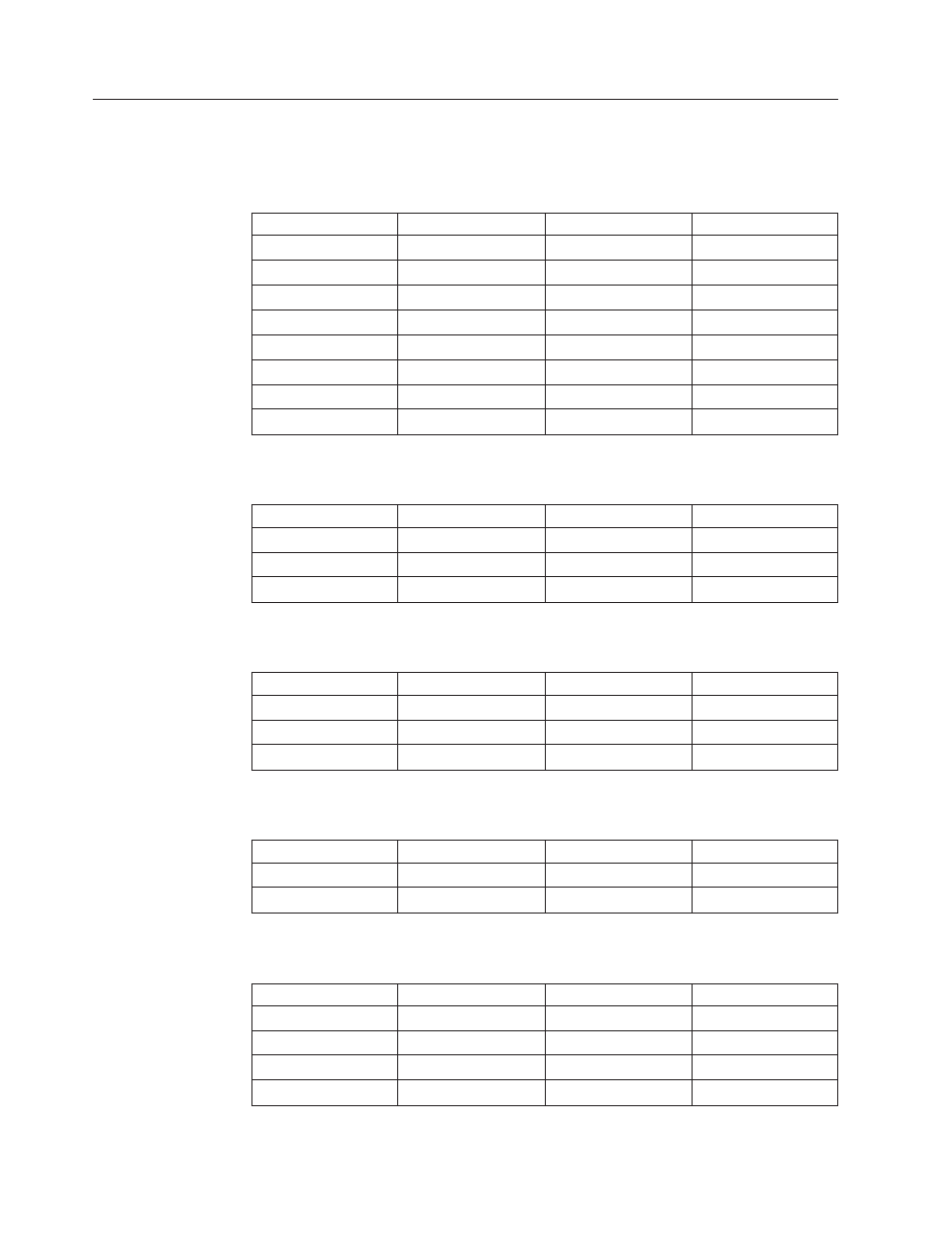
Power
supply
connectors
These
tables
enable
you
to
check
the
power
supply
voltages.
Connector
P1
OUTPUT
CONNECTOR
PINS
WIRE
COLOR
TOLERANCE
+3.3
Vdc
1,
2,
11
Orange
+5%,
-5%
DC
return
3,
5,
7,
13,
15,
16,
17
Black
N/A
+5
Vdc
4,
6,
19,
20
Red
+5%,
-5%
Power
Good
8
Gray
N/A
+5
AUX
9
Purple
+5%,
-5%
+12
Vdc
10
Yellow
+5%,
-5%
-12
Vdc
12
Blue
+10%,
-10%
On/Off
14
Green
N/A
Connector
P2,
P3,
P4,
and
P7
OUTPUT
CONNECTOR
PINS
WIRE
COLOR
TOLERANCE
DC
return
2,
3
Black
N/A
+5
Vdc
4
Red
+5%,
-5%
+12
Vdc
1
Yellow
+5%,
-5%
Connector
P5
(Diskette
drive)
OUTPUT
CONNECTOR
PINS
WIRE
COLOR
TOLERANCE
DC
return
2,
3
Black
N/A
+5
Vdc
1
Red
+5%,
-5%
+12
Vdc
4
Yellow
+5%,
-5%
Connector
P6
OUTPUT
CONNECTOR
PINS
WIRE
COLOR
TOLERANCE
DC
return
1,
2
Black
N/A
+12
Vdc
3,
4
Yellow
+5%,
-5%
Connector
P8
(Serial
ATA)
OUTPUT
CONNECTOR
PINS
WIRE
COLOR
TOLERANCE
DC
return
2,
4
Black
N/A
+12
Vdc
1
Red
+5%,
-5%
+5
Vdc
3
Yellow
+5%,
-5%
+3.3
Vdc
5
Orange
+5%,
-5%
110
Hardware
Maintenance
Manual