6 connectors, 1 chassis intrusion switch connector: jci1, 2 44-pin eide connector: ide1 – Intel AIMB-253 User Manual
Page 24: Figure 2.5: 44-pin eide connector: ide1, Connectors, Chassis intrusion switch connector: jci1 figure, 4 chassis intrusion switch connector: jci1, Pin eide connector: ide1 figure, 5 44-pin eide connector: ide1
AIMB-253 User Manual
14
2.6
Connectors
2.6.1
Chassis Intrusion Switch Connector: JCI1
This connector connects to a 2-pin chassis switch. If the chassis is
opened, the switch will be short. The system will record this status and
show a warning message on the screen. To clear the warning, you must
enter the BIOS utility and clear the record.
Figure 2.4: Chassis Intrusion Switch Connector: JCI1
2.6.2
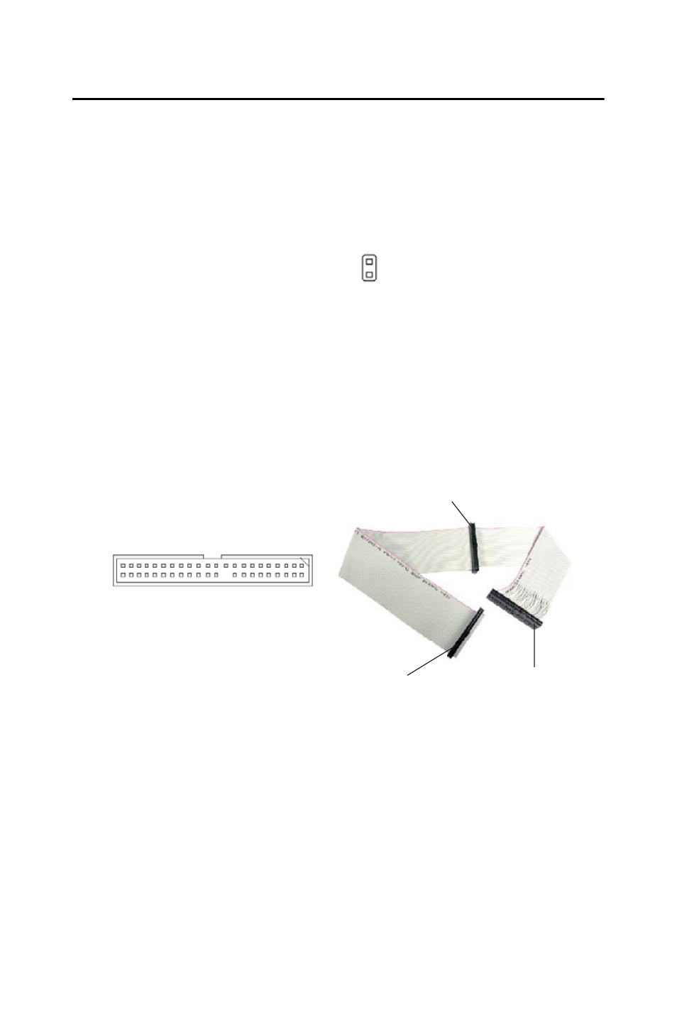
44-Pin EIDE Connector: IDE1
This 44-pin EIDE connector connects to an optional converter that
enables connection to one 44-pin EIDE device and one 40-pin EIDE
device, such as hard disk drives, CD- ROM and other EIDE devices.
Figure 2.5: 44-Pin EIDE Connector: IDE1
Note
If you install two hard disks on cable, you must configure the
second drive to Slave mode by setting its jumper. Refer to the
hard disk documentation supplied by hard disk vendors for
jumper setting instructions.
JCI1
1
2
CHASSIS
GND
IDE1
Connect to EIDE1
Connect to 40-pin
EIDE device
Connect to 44-pin
EIDE device