MGE UPS Systems EX 7RT User Manual
Page 44
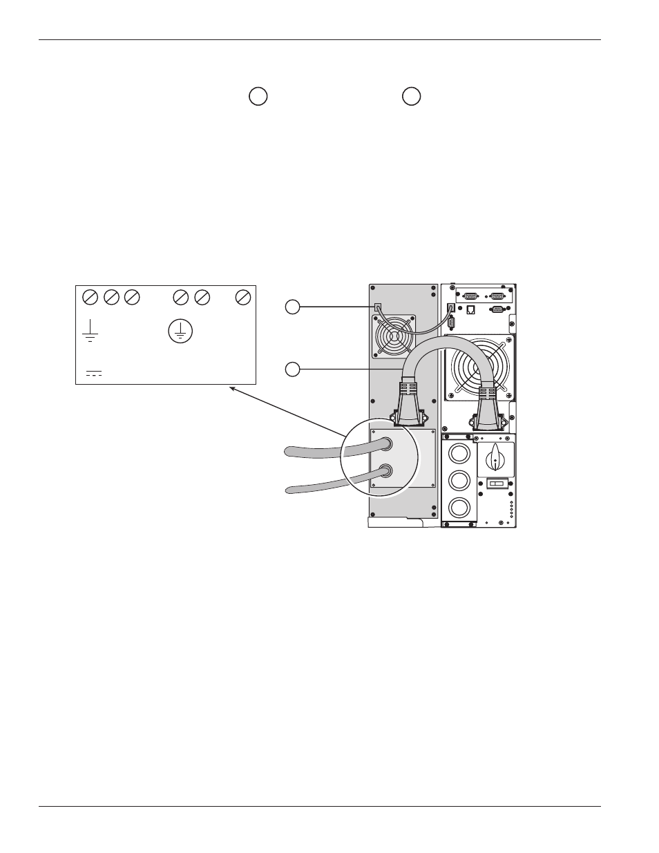
2.10
Connection of CLA Module
1.
Connect the battery power cable
and battery detection cable
(provided with the CLA module)
between the power module and the CLA module.
2.
Connect the DC Input of the CLA to high power battery cabinet.
◗ DC Input Cable cross-section (not provided): maximum 4 AWG solid or stranded wire.
3.
Connect the AC input cable of the CLA module to the utility AC input:
◗ AC input cable cross-section (not provided): maximum 16 AWG solid or stranded wires.
Figure 2-18: Rear view of CLA module cable battery and AC input connections.
42
40
EX 5/7/11 RT System
Installation
2 — 20
86-86000-00 A01
To High
Power Battery
Cabinet
Utility AC Source
42
40
Connection Diagram
(inside CLA Module)
- +
DC INPUT
240Vdc
N L
(L2) (L1)
AC INPUT
156-280Vac