Ex 5/7/11 rt system – MGE UPS Systems EX 7RT User Manual
Page 32
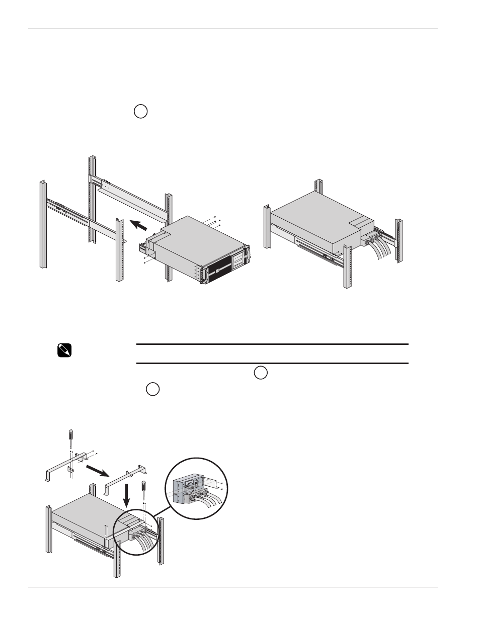
2.6.1
Rear Support Brackets Installation
(Part number 86013, included with rack mounting kits, part numbers: 86001 and 86002)
These brackets prevent the power module from moving when the entire rack enclosure is moved.
Proceed as follows:
1.
Attach the brackets
to the I/O Box and power module.
2.
Secure brackets to rails.
Figure 2-7a: Rear Support Brackets.
2.6.2
Input/Output Box Bracket System Installation
(Part number 86012 included with power module rack mounting kit, part numbers: 86001)
This bracket system keeps the I/O Box stationary while hot swapping the power module. It will then be easier to slide
the replacement module into the connectors of the I/O Box.
NOTE:
The rear support brackets must be removed prior to
installing I/O Box bracket system.
1.
Secure small bracket to larger bracket from the underside
.
2 & 3. Secure large bracket
(with supplied screws) to rails at the rear of module.
4.
Secure small attached bracket (with supplied screws) to the I/O Box.
Figure 2-7b: Input/Output Box Bracket System.
27
27
25
EX 5/7/11 RT System
Installation
2 — 8
86-86000-00 A01
1
1
2
2
OFF
1
2
3
3
4
4