MGE UPS Systems EX 7RT User Manual
Page 43
Installation and User Manual
2.9
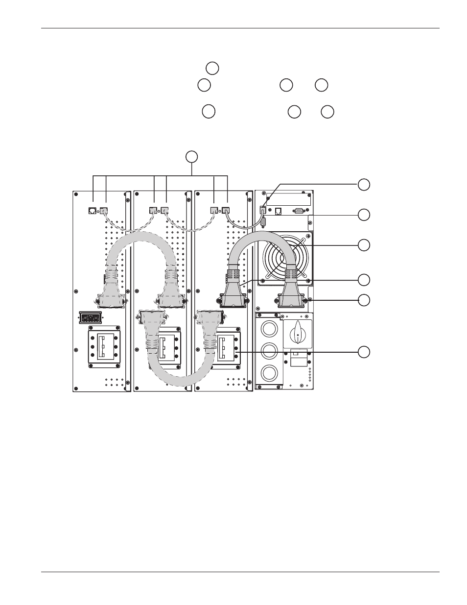
Connection of Battery Module, EXB
1.
Check that the battery circuit breaker
is OFF (“0”) position.
2.
Connect the battery power cable
to the connectors
and
of the power and battery
modules.
3.
Connect the battery detection cable
between connectors
and
of the power and battery
modules.
Figure 2-17: Rear view of battery module cable connections.
12
4
42
13
6
40
14
Installation
2 — 19
86-86000-00 A01
4
42
40
13
14
6
12
See also other documents in the category MGE UPS Systems Tools:
- Pulsar EX 1000 (28 pages)
- 4.5 kVA (32 pages)
- 1100 (196 pages)
- EPS 8000 (54 pages)
- S EXB 2500 (22 pages)
- Pulsar Extreme 3200C (28 pages)
- ESV 22+Rack (24 pages)
- GES-801L (22 pages)
- Comet EX 7 RT 3:1 (38 pages)
- Galaxy PW (44 pages)
- 3 (34 pages)
- Pulsar TM 30 (18 pages)
- 22+ EB 22 (44 pages)
- 1500C (28 pages)
- Rackmount PDU (36 pages)
- Pulsar Esprit 313.5 kVA (6 pages)
- EX-5 (76 pages)
- 30A (30 pages)
- AmpMeter PDU (52 pages)
- EX30 (106 pages)
- 1100 Tower (36 pages)
- 40-75KVA (56 pages)
- 2000 (34 pages)
- 4000 RT (38 pages)
- Pulsar EXtreme C UPS 1500 VA (4 pages)
- FlexPDU 6 AUS (12 pages)
- POWER-SURE 700 (52 pages)
- 250A (34 pages)
- EX 1000 (28 pages)
- EX7 (18 pages)
- EX30Rack (24 pages)
- 12280 kVA (13 pages)
- 40-150kVA (56 pages)
- 100 (32 pages)
- Uninterruptible Power Provider (4 pages)
- EPS 7000 (62 pages)
- 300 (6 pages)
- EX10Rack (22 pages)
- 500 (4 pages)
- EPS 6000 (84 pages)
- S3 (64 pages)
- EX RT CLA (6 pages)
- 3000 (32 pages)
- 3.5 to 21 kVA N+1 (54 pages)