Installation for vertical termina- tion, Fp1969 offset w/ wallstrap, Flat ceiling installation – Monessen Hearth LEXINGTON LX32DV User Manual
Page 21
51D0528
21
LX Series Direct Vent Gas Fireplace
VeNtING INStALLAtIoN
FP1183
max height
10' Maximum
40'
Maximum
Height
8'
Minimum
Height
Support
Straps
Every 5'
Vertical
Support Straps Every 3'
10' Maximum
40'
Maximum
Height
8'
Minimum
Height
Support Straps Every 3'
FP1183
Figure 27 -
Support Straps for Horizontal Runs
1
2
3
4
1
2
3
4
FP1179
max bends
Example: Elbow 1 = 90°
Elbow 2 = 45°
Elbow 3 = 45°
Elbow 4 = 90°
Total Angular = 270°
Variation
FP1179
Figure 28 -
Maximum Elbow Usage
INStALLAtIoN FoR VeRtIcAL teRMINA-
tIoN
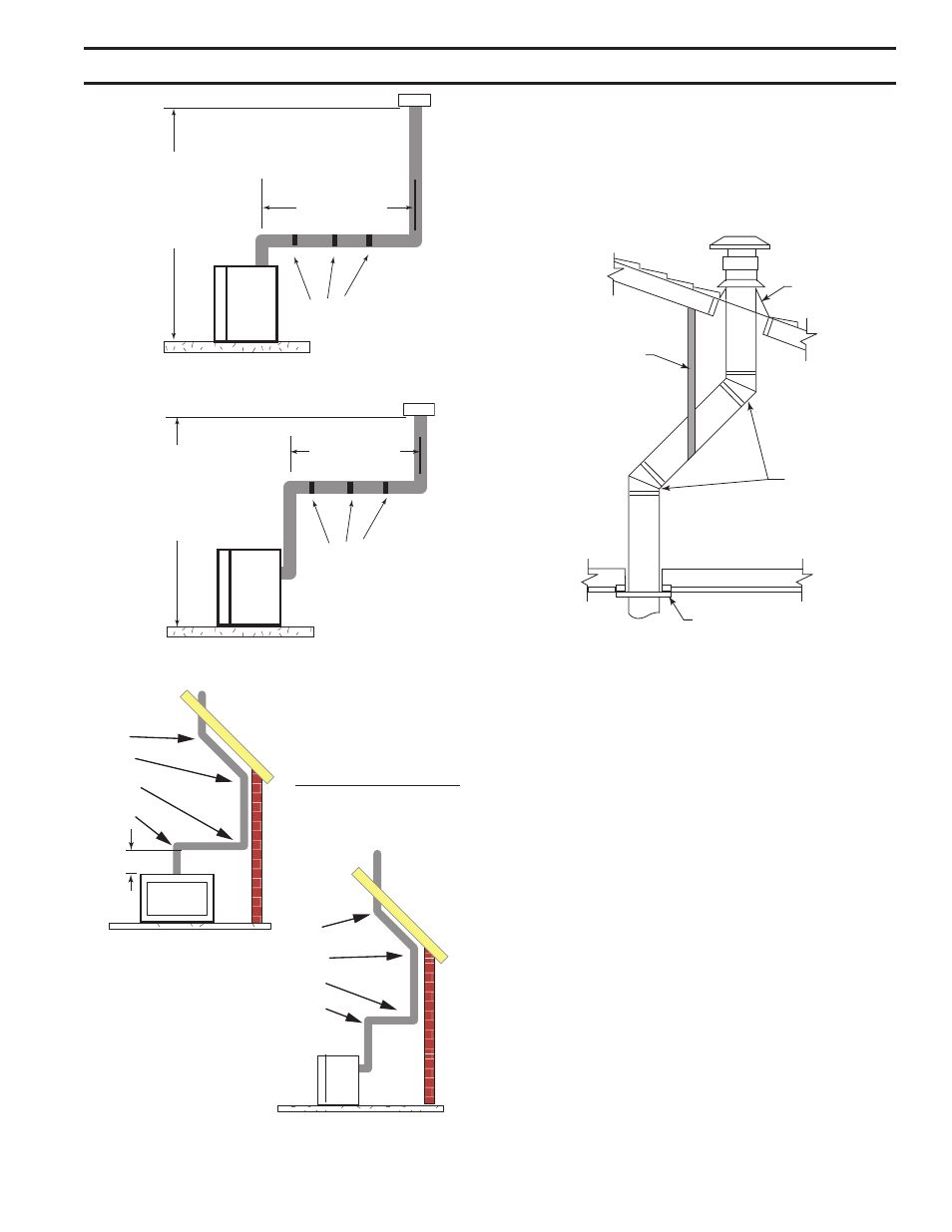
1. Determine the route your vertical venting will take. If
ceiling joist, roof rafters or other framing will obstruct the
venting system, consider an offset. Figure 29 to avoid
cutting load bearing members.
FP1969
offset w/ wallstrap
Figure 29 -
Offset with Wall Strap and 45° Elbows
Roof Flashing
Wall Strap
45° Elbows
Ceiling Firestop
FP1669
Note: Pay special attention to these installation instructions
for required clearances (air space) to combustibles when
passing through ceilings, walls, roofs, enclosures, attic
rafters, etc. Do not pack air spaces with insulation. Also
note maximum vertical rise of the venting system and any
maximum horizontal offset limitations. Offsets must fall
within the parameters shows on Page 16, Figure 13.
2. Set fireplace in desired location. Drop a plumb line down
from the ceiling to the position of the flue exit. Mark the
center point where the vent will penetrate the ceiling.
Drill a small locating hole a this point.
Drop a plumb line from the inside of the roof to the ceiling
locating hole in the ceiling. Mark the center point where
the vent will penetrate the roof. Drill a small locating hole
at this point.
FLAt ceILING INStALLAtIoN
1. Cut a 9Z\x" (241 mm) square hole in the ceiling using the
locating hole as a center point The opening should be
framed to 9Z\x" x 9Z\x" (241 x 241 mm) inside dimensions
as shown in Figure 31 using framing lumber the same
size as the ceiling joist. If the area above the ceiling is
an insulated ceiling or a room, nail firestop from the top