Warning – Monessen Hearth LEXINGTON LX32DV User Manual
Page 18
18
51D0528
LX Series Direct Vent Gas Fireplace
VeNtING INStALLAtIoN
HOT
FP2715
horiz cap w shield
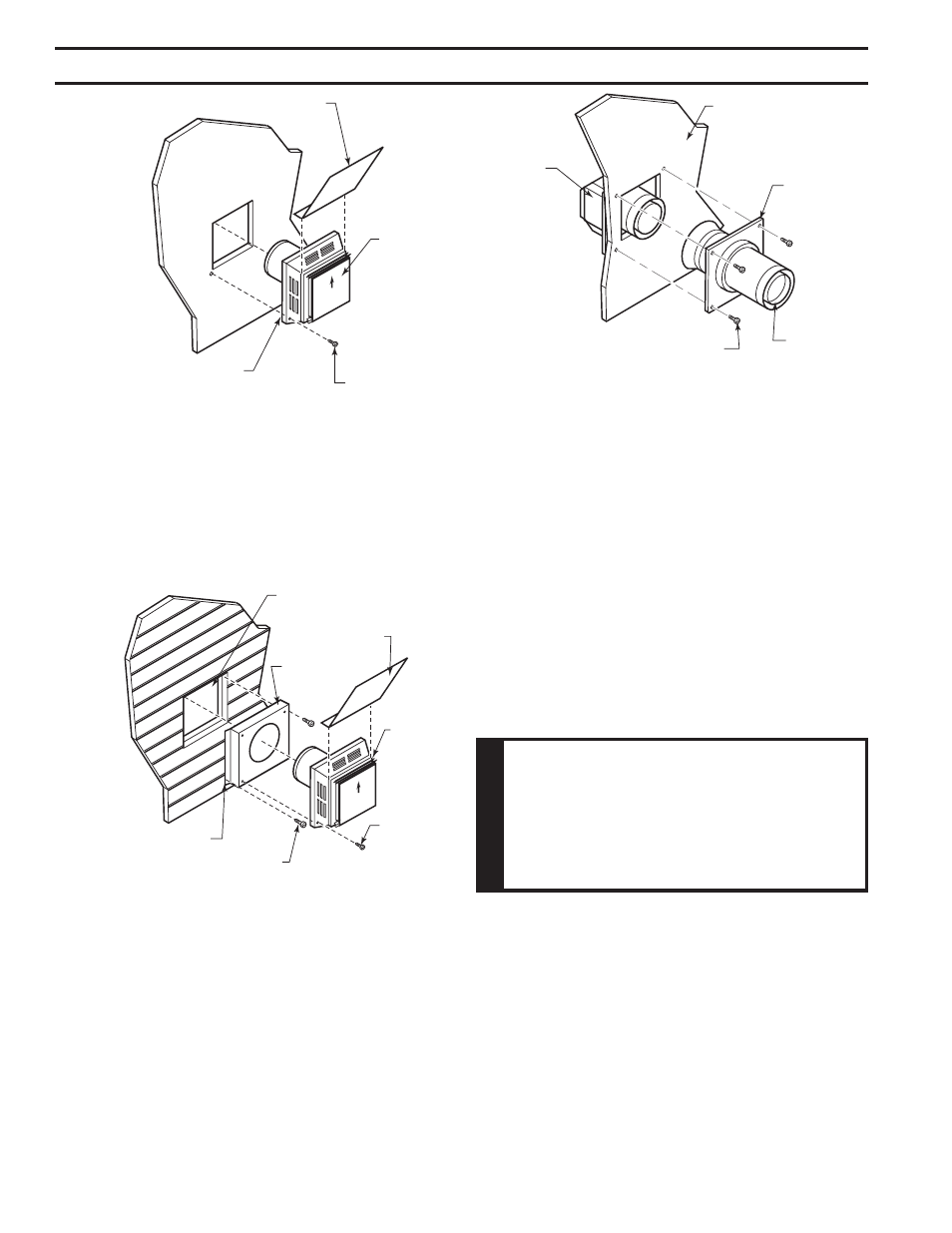
Figure 17 -
Installing Horizontal Vent Cap
Vent Cap
Apply Mastic to
All Four Sides
Deflecting Shield
Wood Screw
FP2715
For vinyl siding, stucco, or wood exterior use vinyl siding
standoffs between vent cap and exterior wall. The vinyl
siding standoff prevents excessive heat from melting the
vinyl siding material. Bolt the vent cap to the standoff. Apply
non-hardening mastic around outside edge of the standoff
instead of the vent cap assembly. Use wood screws pro-
vided to attach the standoff. Figure 18
HOT
Fp2716
vinyl siding standoff
Figure 18 -
Install Vinyl Siding Standoff
Apply Mastic to
All Four Sides
Cut Vinyl Siding Away
to Fit Standoff
Wood Screw
Vent
Cap
Screw
Standoff
Deflecting Shield
FP2716
FP1957
install firestop
Figure 19 -
Connect Vent Cap with Horizontal Vent Pipe
Interior Wall
Surface
Fire Stop
Assembly
Horizontal
Vent Pipe
Screw
Vent Cap
(Horizontal
Termination)
FP1957
hoRIZoNtAL (thRouGh the WALL) teR-
MINAtIoN coNFIGuRAtIoNS
Since it is very important that the venting system main-
tain its balance between the combustion air intake and
the flue gas exhaust, certain limitations as to vent con-
figurations apply and must be strictly adhered to.
The Vent Graph, showing the relationship between vertical
and horizontal side wall venting, will help to determine the
various dimensions allowable. Refer to Page 16
Minimum clearance between vent pipes and combus-
tible materials is 3" on top and 1" from bottom and
sides unless otherwise noted.
When vent termination exits through foundations less than
20" below siding outcrop, the vent pipe must flush up with
the siding.
It is best to locate the fireplace in such a way that minimizes
the number of offsets and horizontal vent length.
W
ARNING
When installing the appliance as a rear
vent unit, the 90°, 45° transition elbow
attached directly to the rear of the unit is
Not INcLuDeD in the following criteria
and calculations, and unless specifically
mentioned should be ignored when
calculating venting layouts.
The horizontal vent run refers to the total length of vent
pipe from the flue collar of the fireplace (or the top of the
Transition Elbow) to the face of the outer wall.
•
The maximum number of 90° elbows per side wall
installation is three (3). Figure 20
•
If a 90° elbow is fitted directly on top of the fireplace
flange the maximum horizontal vent run before the ter-
mination or a vertical rise is 36” (914 mm). Figure 21
•
If a 90° elbow is used in the horizontal vent run (level
height maintained) the horizontal vent length is reduced
by 36" (914 mm). This does not apply if the 90° elbows
are used to increase or redirect a vertical rise. Figure
23
5. Slide fire stop over the vent pipe before connecting the
horizontal run to the vent cap. Figure 19
6. The pipe overlap should be a minimum of 1Z\v". Apply
silicone to the outer pipe connection. Fasten all vent
connections with screws provided.
7. Slide fire stop against the interior wall surface and attach
with screws. Figure 19