Miller Electric IH User Manual
Page 68
OM-203 185 Page 64
8-5-6.
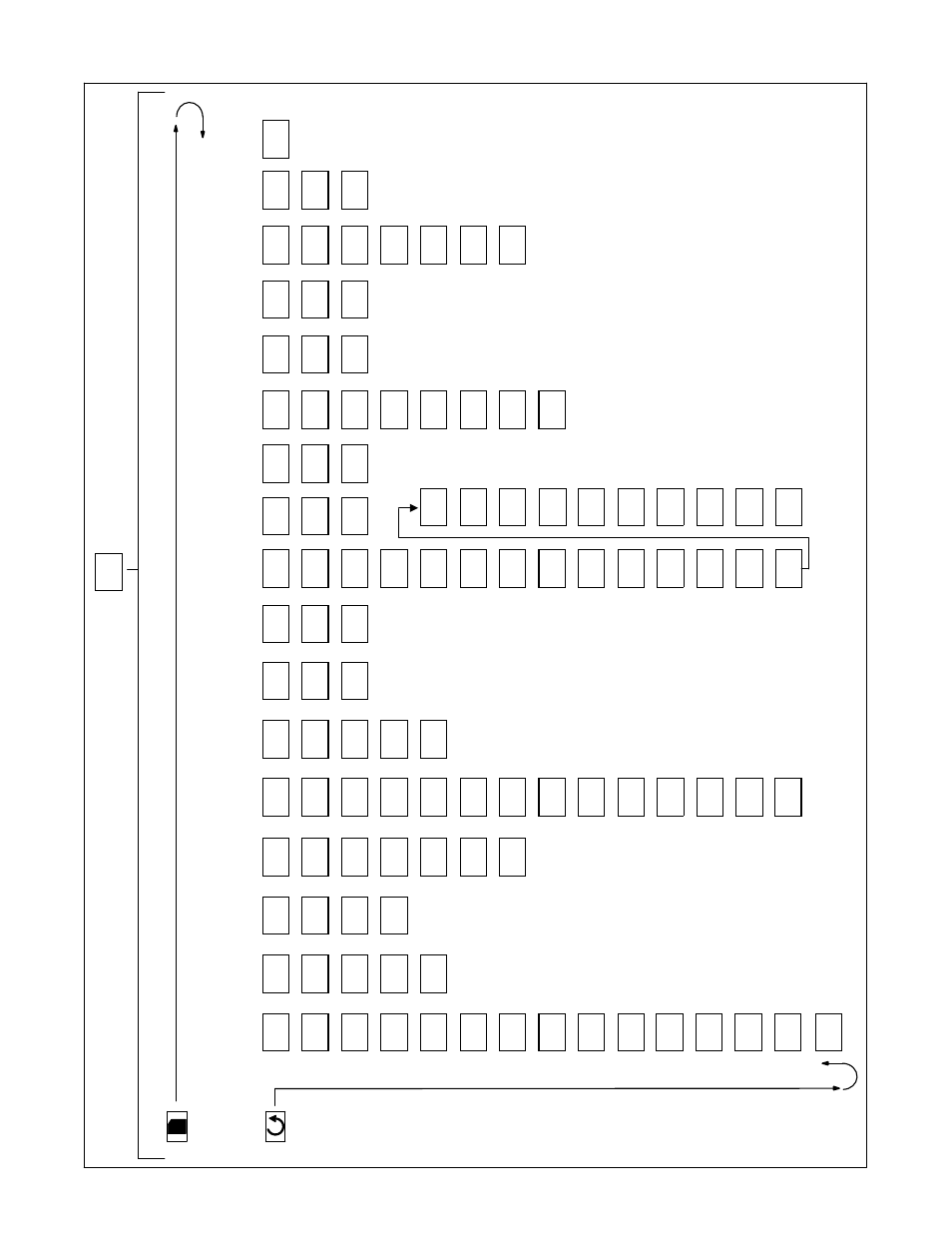
2408 Controller Configure Parameters (Effective w/Version V4.09)
Goto
conF
Process
Logical
Logical
Alarm
Instrument
Value
Input
Setpoint
Alarms
Programmer
Inputs A
Inputs B
relay
Comms 1
Comms
2
Module 1
Module 2
Module
3
Calibration
P
as
sw
or
d
Config
Config
Config
Config
Config
Config
Config
Config
Config
Config
Config
Config
Config
Config
Config
Config
inSt
PV
iP
SP
AL
PROG
LA
L
b
AA
HA
J
A
1A
2A
3A
CAL
PASS
Exit
ConF
ConF
ConF
ConF
Conf
ConF
ConF
ConF
ConF
Conf
Conf
C
o
n
F
C
o
n
F
C
o
n
F
ConF
ConF
n
o
CtrL
unit
inPt
nSP
AL 1
PtyP
id
id
id
id
id
id
id
id
rcAL
ACC.P
Pid
%
f
k.
tc
2
d
H
i
1
LoG.I
LoG.I
rELy
none
none
d
c.OP
none
none
none
1
A
c
t
dEc.P
CJC
rm.tr
Ltch
HbAc
Func
Func
Func
Func
Func
Func
Func
Func
UCAL
cnF.P
r
E
v
nnnn
Auto
OFF
n
o
ProG
r−H
r
E
S
di
G
none
none
H
E
A
T
none
none
no
2
COOL
rnG.L
i
m
P
m.tr
bLoc
Pwr.
F
SEnS
VAL.L
Pt1.L
Lin
0
Auto
OFF
n
o
rSEt
n
o
r
0
0
ti.
td
rnG.
H
Pr.
tr
A
L
2
Srvo
1dHi
V
AL.H
Pt1.H
Sec
1450
O
F
F
O
F
F
to.PV
YE
S
1
0
0
1000
dtyP
rmP.U
Ltch
AL 2
unit
OF1.L
E
r
r
Pmin
n
o
n
o
voLt
0.
0
m−A
rmt
bLoc
A
L
3
O
ut.L
OF1.H
diSA
none
no
no
0.
0
0.
0
r−h
AL 3
AL 4
O
ut.H
diSA
OFF
n
o
10.0
PwrF
Ltch
m
A
n
dc.F
O
F
F
no
no
no
Fwd.t
bLoc
Sbr
rmt.F
nonE
n
o
n
o
n
o
LCiHi
AL 4
SPAn
iP1.
F
100
O
F
F
no
no
Sbr.t
Ltch
L
b
r
nw.AL
Sb.OP
no
no
no
FOP
bLoc
Ld.F
End
no
no
no
YE
S
bcd
Htr.F
Sync
none
no
no
Gsch
no
Navigation
Page
Across
Scroll Down
.
Refer
to Section
8-5
for additional navigation instructions.
Sbr.
t
EnAb
tunE no
Ct.OP
no
Ct.Sh
no
SSr.F
no