Figure 6-2 and figure 6-3, Seg.n 1 type step tgt 600, Seg.n 3 type dwel dur 0.5 – Miller Electric IH User Manual
Page 27: Seg.n 4 type rmp.r tgt 600, Seg.n 5 type end end.t s op, Rate 600
OM-203 185 Page 23
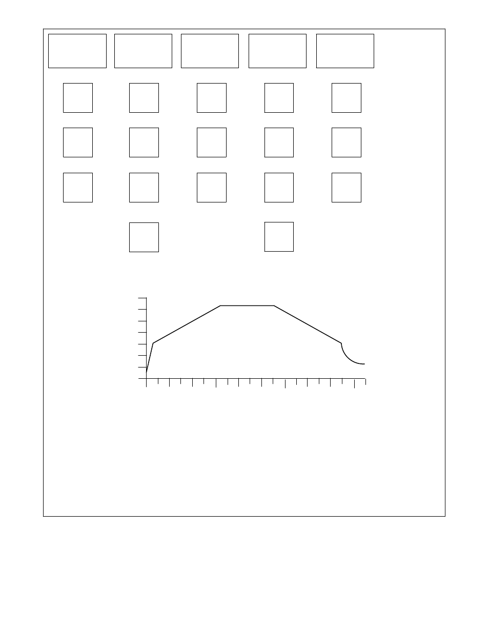
Step to 600
°
F
as fast as
possible*
Ramp to 1350
°
F
@ 600
°
/hr
SEG.n
1
tYPE
StEP
tGt
600
(step)
(deg)
SEG.n
2
tYPE
rmP.r
tGt
1350
(ramp rate)
SEG.n
3
tYPE
dwEl
dur
0.5
(soak)
(in hrs)
0
200
400
600
800
1000
1200
1400
0
30
60
90
120
150
180
Time (minutes)
Degrees F
Example Stress Relief Profile
SEG.n
4
tYPE
rmP.r
tGt
600
(ramp rate)
Free fall to
ambient
SEG.n
5
tYPE
End
End.t
S OP
(end)
(sets output to 0)
rAtE
600
(deg)
(deg/ hr)
rAtE
600
(deg)
(deg/hr)
Dwell @ 1350
°
F for 1/2 hour
Ramp to 600
°
F
@ 600
°
/hr
210
240
270
.
*On small diameter pipe, it may be necessary to reduce the
output of the power source to achieve a “reasonable rate” in
Segment 1; thereafter, the program controls the rate of
temperature rise and the output power may be increased to
full if desired. To reduce output power, turn power source
output knob to desired setting.
Figure 6-2. Setting Stress Relief Profile Using Example Parameters