3. connecting to power source, 4. input 14 pin information for receptacle rc1 – Miller Electric IH User Manual
Page 13
OM-203 185 Page 9
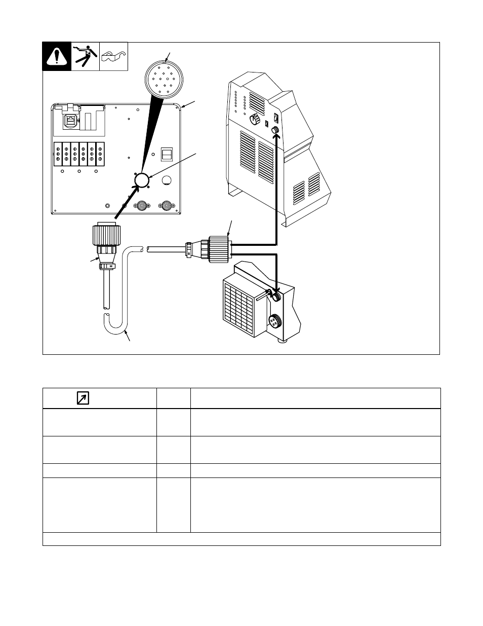
4-3. Connecting To Power Source
Turn Off power source.
1. IH/TS
2. Interconnecting Cord
3. 14-Socket Plug
4. 14-Pin Plug
Obtain cord with 14-socket plug on
one end and 14-pin plug on other
end.
5. Keyway
6. Remote 14 Receptacle RC1
To connect cord to a receptacle,
align keyway, insert plug, and
tighten threaded collar.
To connect remaining end of cord to
power source, align keyway, insert
plug, and tighten threaded collar.
2
sb7.1* 3/93 - Ref. S-0004-A / S-0750 / Ref. 802 926 / Ref. 801 049 / 801 825-B / Ref. 803 004-A
3
4
1
6
J
A
I
K
B
H N L
C
G M
D
F E
5
4-4. Input 14 Pin Information For Receptacle RC1
REMOTE 14
Pin
Pin Information
Remote Contactor
A
+24 volts dc from power source.
Remote Contactor
B
Contact closure to A completes power source +24 volts dc contactor control circuit.
Remote Output Control
D
Control circuit common.
Remote Output Control
E
0 to +10 volts dc signal for power source output control.
Power Source Fault
F, J
Absence of contact closure from power source indicates power source output failure.
I
Actual frequency input signal.
Remote Metering*
L
Average power input signal.
Remote Metering*
M
Voltage input signal RMS.
N
Current input signal RMS.
*See power source Owner’s Manual for scaling information.