4 plc mounting arrangements, 4 montage de l’api, 4 montage der sps – Mitsumi electronic FX2N User Manual
Page 46: 4 montaggio del plc, Plc mounting arrangements -8, Montage de l’api -8, Montage der sps -8, Montaggio del plc -8, Montage der sps 3.4, Montage de l’api 3.4
FX2N Series Programmable Controllers
Installation 3
3-8
3.4
PLC mounting arrangements
PLC mounting arrangements
3.4
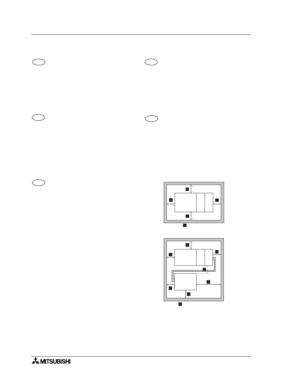
To prevent a rise in temperature, mount the units to
walls. Never mount them to the floor or ceiling of an
enclosure.
Figure 3.2
Single row arrangement
Figure
3.3 Double row arrangement using
extension cable FX
0N
-65EC /FX
0N
-
30EC(650mm (25.59 inches) /300mm
(11.81 inches); supplied separately).
Montage der SPS
3.4
Zur Verhinderung eines Temperaturanstiegs sollten
die Geräte an der Schaltschrankrückwand montiert
werden. Es darf auf keinen Fall eine Montage am
Boden oder an der Decke des Schaltschranks
erfolgen.
Figure 3.2
Einfache Reihenanordnung
Figure
3.3 Doppelte Reihenanordnung durch
Einsatz der Erweiterungskabel FX
0N
-
65EC oder FX
0N
-30EC (650 mm / 300
mm); nicht im Lieferumfang enthalten).
Montaje de la unidad de mando de
memoria programable PLC
3.4
Para evitar un aumento de temperatura, las unidades
se deberán montar en la pared dorsal del armario de
distribución. En ningún caso se deberá efectuar un
montaje sobre el suelo o en el techo del armario de
distribución.
Figure 3.2
Disposición en línea simple
Figure 3.3
Disposición en línea doble mediante el
empleo del cable de ampliación
FX0N-65EC ó FX0N-30EC (650 mm /
300 mm)
Montage de l’API
3.4
Les appareils doivent être montés sur le panneau
arrière de l’armoire électrique pour empêcher une
augmentation de la température. En aucun cas les
appareils ne doivent être montés sur le fond ou au
plafond de l’armoire électrique.
Figure 3.2
Montage en série simple
Figure 3.3
Montage en série double en utilisant le
c â ble d ’ex t e n s io n F X 0 N - 6 5 E C o u
FX0N-30EC (650 mm / 300 mm)
Montaggio del PLC
3.4
Per ev it a re u n au m en to d ella t em pe rat ura, si
dovrebbero montare gli apparecchi alla parete
dell’ar m adio elettr ico. In nessun caso si deve
eseguire un montaggio sul pavimento o al soffitto
dell’armadio elettrico.
Figure 3.2
Disposizione in fila semplice
Figure 3.3
Disposizione in fila doppia tramite cavo
di ampliamentoFX0N-65EC o FX0N-
30EC (650 mm / 300 mm)
Figure 3.2:
Figure 3.3:
ENG
GER
ESP
FRE
ITL
F X
2 N
C P U
FX
2N
-4
A
D
FX
2N
-8
E
Y
R
> 5 0 m m ( 1 . 9 7 I n c h e s )
)
)
)
)
)
)
F X
2 N
C P U
FX
2N
-4
A
D
FX
2N
-
8E
Y
R
F X 2 N - ? ? E R
( T / S )
> 5 0 m m ( 1 . 9 7 I n c h e s )
)
)
)
)
)
)
)
)