Onnecting, Anagement, Onsole – GE MULTILINK ML1200 User Manual
Page 58: Erminal, Ultilink, Ml1200 (s, Erial, Rj-45 c
3–10
MULTILINK ML1200 MANAGED FIELD SWITCH – INSTRUCTION MANUAL
INSTALLATION
CHAPTER 3: INSTALLATION
3.4.4
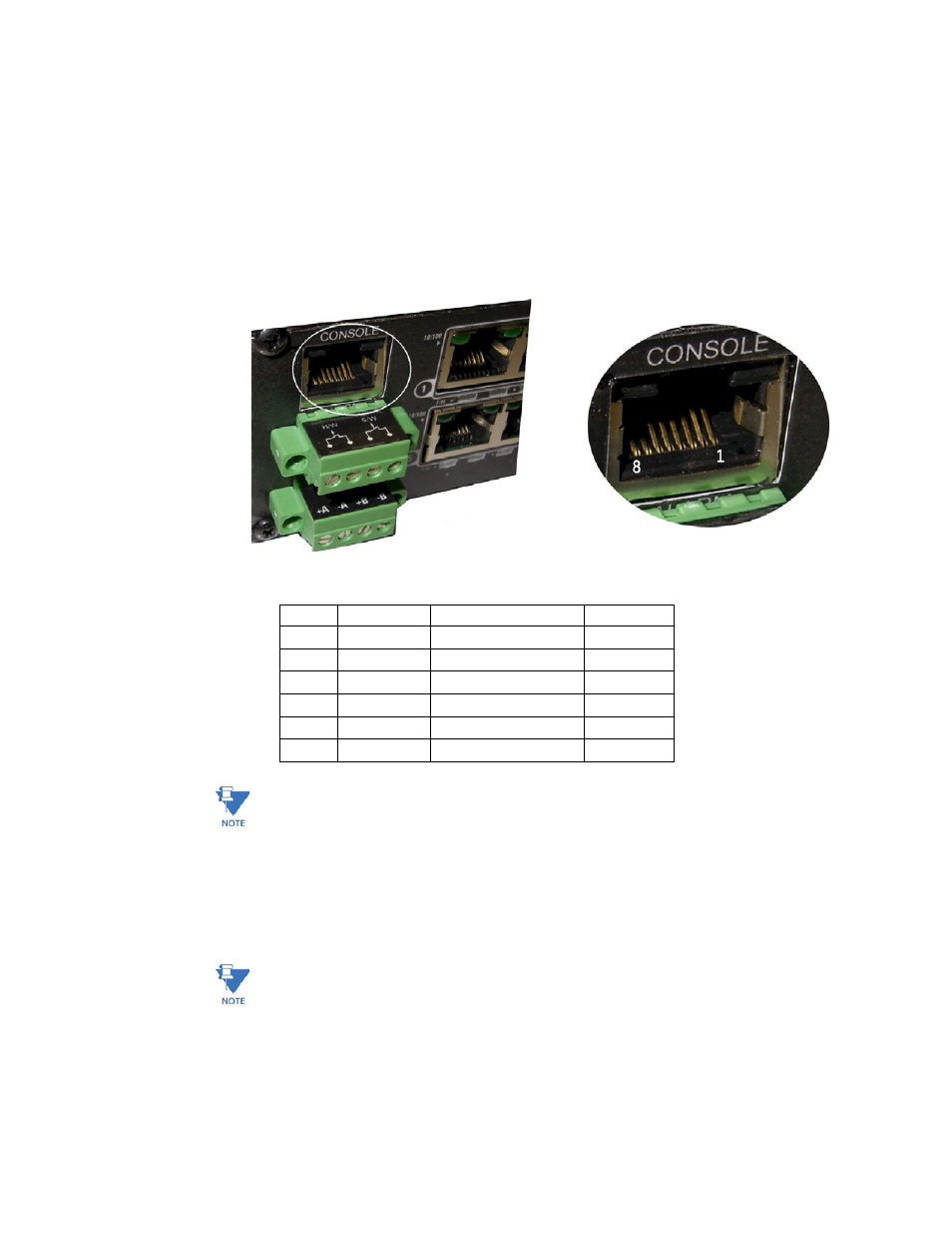
Connecting a Management Console Terminal to Multilink ML1200 (Serial-RJ-45
Console Port)
The serial console port on the Multilink ML1200 is different from other Multilink family
switches. The Serial RJ-45 port, as shown in the picture, requires an 8-pin RJ-45 male
connector to have the proper communication. (Note - the serial RJ-45 console port on the
Multilink ML1200 is compatible with Cisco-type RJ-45 console port cables).
The Serial port pin-out for the RJ-45 console port used on Multilink ML1200 is shown below.
Note
The console RJ-45-Serial cable may be ordered from the Factory, using the model number
and description here:
CONSOLE-CBLQD- Console attachment cable serial null-modem cable with one side RJ-45
for the ML1200 and a male DB-9 Female connector on the other end.
CONSOLE-CBLQU- Console attachment cable serial null-modem cable Combo with one
serial- RJ-45 for the ML1200 side and a USB cable connector option on the other end (e.g
computer).
Note
For Power Substations: In support of the IEEE 1613 Class 2 standard, GE Multilin advises
that, for substation applications, the serial RJ-45console ports are intended for temporary
connectivity to other equipment such as PCs. Since the console port connection is
temporary, it is excluded from IEEE 1613 packet-loss testing per the 1613 standard-
defined test procedure.
Table 3–1: Pinout information for above connector
Pin
Name
Description
Direction
1
RTX
Request to Send
OUT
3
TXD
Transceiver Data
OUT
4
GND
Ground
5
GND
Ground
6
RXD
Receive Data
IN
8
CTS
Clear to Send
IN