9 additional information – Guardian Technologies QUIETPACT 40LP 004701-0 User Manual
Page 11
section 2 – operation
recreational vehicle generator
Figure 2.2 – Low Oil Pressure and
High Temperature Switches
High Temperature Switch
Low Oil Pressure
Switch
2.8.3 FIeld boost
The Controller Circuit Board houses a field boost
diode and resistor that are not part of the automatic
choke circuit. These two components are part of
a “field boost” circuit (Figure 2.3). During engine
cranking only, a positive DC (battery) voltage is
delivered through the diode, resistor, brushes and
slip rings, to the generator rotor. Application of this
voltage to the rotor “flashes the field” whenever it is
started. Flashing of the field each time the generator
starts makes sure that a sufficiently strong magnetic
field is available to produce “pickup” voltage in the
stator windings.
Figure 2.3 – Field Boost Circuit
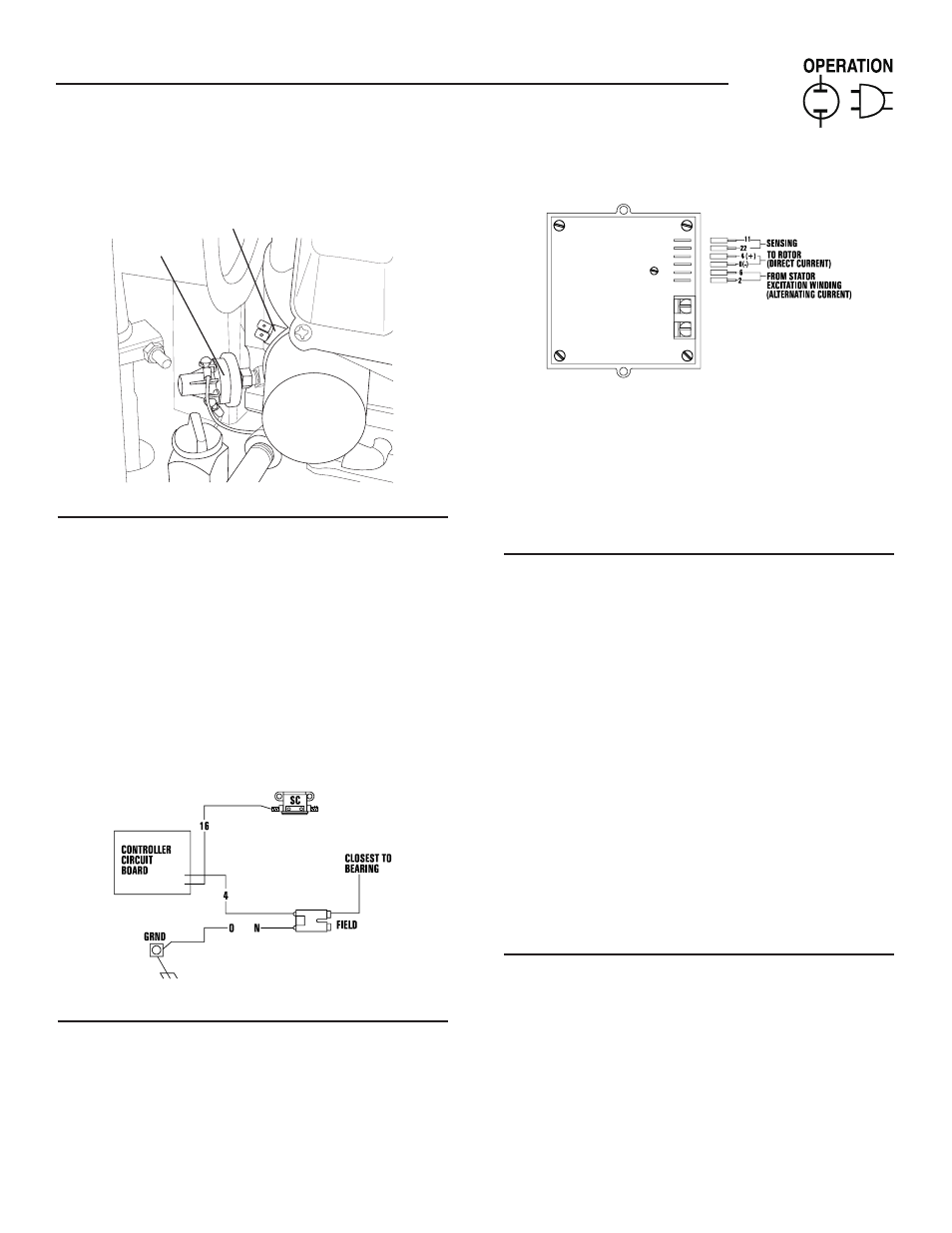
2.8.4 overvoltage protectIon
A solid-state voltage regulator (Figure 2.4) controls
the generator’s AC output voltage. This regulator sup-
plies an excitation current to the rotor. By regulating
the rotor’s excitation current, the strength of its mag-
netic field is regulated and, in turn, the voltage deliv-
ered to connected electrical loads is controlled. When
the AC frequency is 60 Hertz, voltage is regulated at
120 volts (voltage-to-frequency ratio is 2-to-1).
Figure 2.4 – Solid State Voltage Regulator
The voltage regulator also incorporates a “voltage
surge protection circuit.” This circuit prevents trou-
blesome surges in the generator AC output voltage.
Voltage surge is a common cause of damage to elec-
tronic equipment.
2.9 addItIonal InForMatIon
2.9.1 25-hour break-In perIod
The first 25 hours of operation is the break-in period
for the generator. Properly breaking in the genera-
tor is essential to minimize fuel consumption and
provide maximum engine performance. During this
25-hour break-in period, follow this procedure:
• Run the unit at varying electrical loads to help seat
the engine piston rings properly.
• Check the engine oil level frequently. Add oil if
needed. It is normal for the generator engine to
consume more oil than is normal until the piston
rings have properly seated.
• For the 75-hour operation following the break-in
period, avoid light electrical loads. Load the gen-
erator at 50 percent (or more) of its rated watt-
age capacity. Repeated light loads during these 75
hours can cause improper seating of engine piston
rings, resulting in blowby and high oil consump-
tion.
• After operating the unit for 25 hours, complete the
tasks recommended under Section 2.10.2.
2.9.2 25-hour check-up
After the 25-hour break-in period, contact an
Authorized Service Dealer for the following main-
tenance. The vehicle owner is responsible for any
charges:
• Change the engine crankcase oil and oil filter.
• Check the oil level.
• Inspect the cooling and ventilation openings.
• Check the engine carburetor adjustments.
• Check the engine ignition system.
• Inspect the entire electrical system.
• Inspect the engine exhaust system.