Installation instructions, Installation, Logic e-box arrangement of fuel bed components – Stovax PR0741 User Manual
Page 20
INSTALLATION INSTRUCTIONS
INSTALLATION
20
9. LogIC E-Box
ARRANGEMENT OF FUEL BED
COMPONENTS
ADvICE ON hANDLING AND DISPOSAL OF FIRE CERAMICS
The fuel effect and side panels in this fire are made from
Refractory Ceramic Fibre (RCF), a material which is
commonly used for this application.
Preventive clothing is not required when handling these
articles, but we recommend you follow normal hygiene
rules of not smoking, eating or drinking in the work area,
and always wash your hands before eating or drinking.
To ensure that the release of RCF fibres is kept to a
minimum during installation and servicing, a HEPA filtered
vacuum is recommended to remove any dust accumulated
in and around the fire before and after working on it.
When servicing the fire it is recommended that the
replaced items are not broken up, but are sealed within
heavy duty polythene bags and labelled as RCF waste.
RCF waste is classed as stable, nonreactive hazardous
waste, and may be disposed of at a licensed landfill site.
Excessive exposure to these materials may cause temporary
irritation to eyes, skin and respiratory tract; wash hands
thoroughly after handling the material.
NOTE: CERAMIC PARTS ARE FRAGILE. ThE SIDE AND REAR PANELS
ARE REvERSIBLE. ONE SIDE IS PLAIN, ThE OThER SIDE IS REEDED
ONLy USE ThE CORRECT TyPE AND QUANTITy OF CERAMIC
COMPONENTS. ALwAyS FOLLOw ThE FUEL BED LAyOUT AS
STATED IN ThESE INSTRUCTIONS. NEvER ChANGE ThE
LAyOUT FROM ThAT ShOwN hERE.
9.1 Position the burner cover gasket on the burner skin
ensuring the holes align with the ports. Take care as the
front left-hand hole is offset compared to the others,
Diagram 19, arrow A.
19
AR1372
A
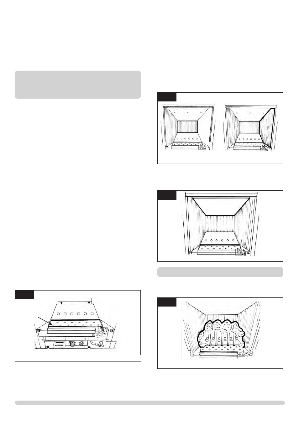
9.2 Place the rear panel against the rear of the box resting on
the shelf. Then slide one of the side panels into the box
ensuring it touches the rear panel. Then gently ease the
front edge of the side panel behind the flange so it lies flat
against the wall of the box. Repeat with the second side
panel., Diagram 20.
20
AR1359
AR1360
9.3 Locate the top panel on top of the sides and rear by lifting
it up and forward inside the box. Then sliding it backwards
and down behind the side panels and resting on the rear
panel, Diagram 21.
21
AR1361
Coal Layout
9.4 Position the flame baffle centrally on the tray and ensure
the stepped lower edge engages against the rear edge of
the burner skin, Diagram 22.
22
AR1362
9.5 Place the front coal centrally in the channel at the front of
the tray. See diagram 7. The relationship between the front
coal and the flame baffle is shown in diagram 23.