Installation instructions, Installation, Installation of the fire – Stovax PR0741 User Manual
Page 17
17
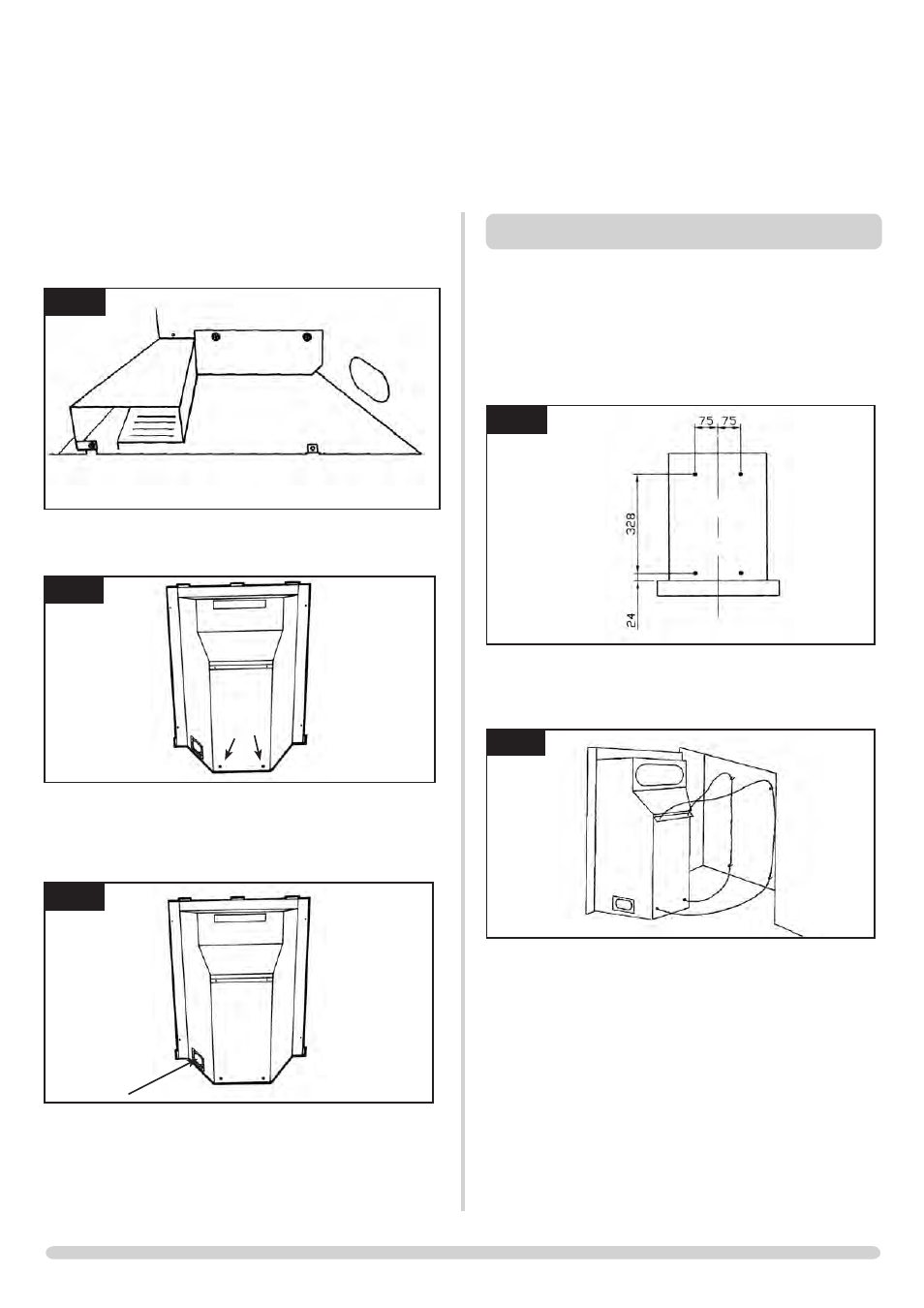
5.3 Decide on the retention method. If cable fixings are to be
used remove the lower cover plate by unscrewing the three
screws., Diagram 3.
3
AR1376
Then remove the two knockout holes on the rear of the box
using a sharp hammer blow, Diagram 4.
4
AR1369
5.4 Remove the backing from the self-adhesive silicone sealing
strip and apply to the rear flange of the firebox ensuring that
it is positioned as close to the outer edge as is practically
possible, Diagram 5.
5
AR1369
5.5 Gas pipe entry must come through the right-hand side of
the box. The rubber seal must be cut using a sharp knife to
allow the isolating elbow to pass through it. Ensure the
rubber is not damaged when doing this.
A means of isolation is provided with the fire. This must be fitted
to the supply pipe prior to installing the firebox.
INSTALLATION INSTRUCTIONS
INSTALLATION
6. InSTaLLaTIon oF THE FIrE
6.1 Ensure that the fireplace opening is in compliance with
Section 2 Site Requirements then proceed as follows:
A) CABLE RETENTION METhOD
6.2 Mark the position of the 4 fixing holes on the rear of the
fireplace opening and drill the holes using a 6.5mm
masonry drill bit. Insert the 4 fibre rawl plugs and screw the
eyebolts in as far as possible leaving the eye horizontal,
Diagram 6.
6
AR1205
6.3 Pass the 2 cables through the holes in the bracket on the
back of the firebox and pull taut so that the stop ends sit
tightly against the top of the bracket, Diagram 7
7
AR1155
6.4 Pass the cables vertically through the 2 sets of eyebolts and
thread the ends through the holes in the lower back of the
firebox. Pass the gas supply pipe through the hole in the
rubber seal (refer to section 5.5) and push the fire into
place.
6.5 Thread the cables through the tensioner bolts and push the
threaded portions through the holes in the firebox so that
the lock nut sits against the back wall (ensure that the nut is
screwed fully up to the head of the tensioner to allow
maximum adjustment).
6.6 Slide the locking nipples onto the cables, pull the cables taut
and tighten the locking screw. Adjust the lock nuts using a
10mm spanner until the silicone sealing strip forms a tight
seal between the fireplace opening and the firebox flange,
Diagram 8