Cable and connector requirements, Installing dc pems, Figure 16 – Force10 Networks Force10 TeraScale E-Series E1200i User Manual
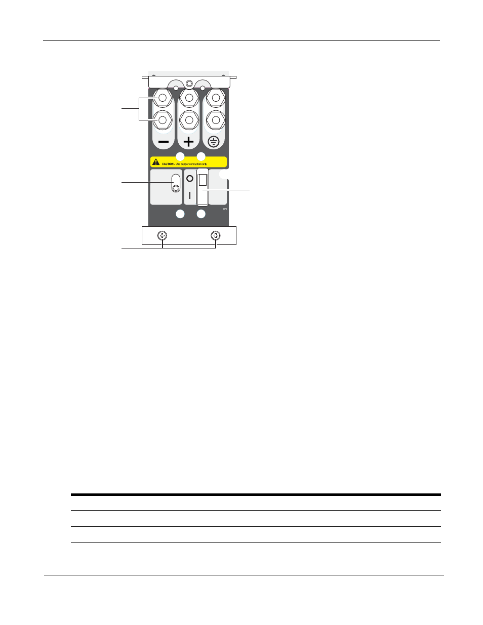
Page 42: E1200i dc pem front panel
42
Installing DC Power Supplies
Figure 16 E1200i DC PEM Front Panel
Cable and Connector Requirements
You must provide your own cables to connect to a remote power source (for example, a circuit breaker
panel) in your equipment rack or office. Cables must be sized to meet the following criteria:
•
rated for at least 150A service to allow for a fully loaded E1200i DC system at low input voltage per
your local electrical codes
•
limits voltage drop across the cable length to 0.5V or less
Before you make the cable connections, apply a coat of antioxidant paste to un-plated metal contact
surfaces. File un-plated connectors, braided straps, and bus bars to a shiny finish. It is not necessary to file
and coat tinned connectors or other plated connection surfaces, such as on the E1200i DC PEM studs.
Installing DC PEMs
Each E1200i DC system requires at least one load-sharing DC PEM to operate. Two units are
recommended for full facility redundancy.
Parameter
Specifications
Maximum DC PEM Input Current
150A
Maximum Power Dissipation
6850W (21,598 BTU/hour)
Input Voltage
-48 to -60 Vdc
CC-E1200-PWR-DC
-48/-60Vdc
150A, 7200VA
Status
Latch Release
PEM interlock
lever
Over-current protector
Locking screws
Studs
FN00102lp