3 operator panel, Operator panel – FUJITSU SPARC ENTERPRISE M5000 User Manual
Page 47
Chapter 2
Fault Isolation
2-9
2.3
Operator Panel
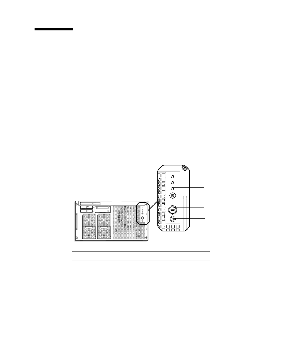
When no network connection is available the operator panel is used to start or stop
the server. The operator panel displays three LED status indicators, a Power switch,
and a security keyswitch. The panel is located on the front of the server, in the upper
right.
When the server is running, the Power and XSCF STANDBY LEDs (green) should be
lit and the CHECK LED (amber) should not be lit. If the CHECK LED is lit, search
the system logs to determine what is wrong.
The three LED status indicators on the operator panel provide the following:
■
General system status
■
System problem alerts
■
Location of the system fault
show the operator panel.
FIGURE 2-3
SPARC Enterprise M4000 Operator Panel
l
Location Number
Component
1
POWER LED
2
XSCF STANDBY LED
3
CHECK LED
4
Power switch
5
Mode switch (keyswitch)
1
2
3
4
5
6