E.3 signal line configuration, Signal line configuration – FUJITSU SPARC ENTERPRISE M5000 User Manual
Page 296
E-2
SPARC Enterprise M4000/M5000 Servers Service Manual • August 2009
E.3
Signal Line Configuration
This section describes signal definitions and electrical specifications.
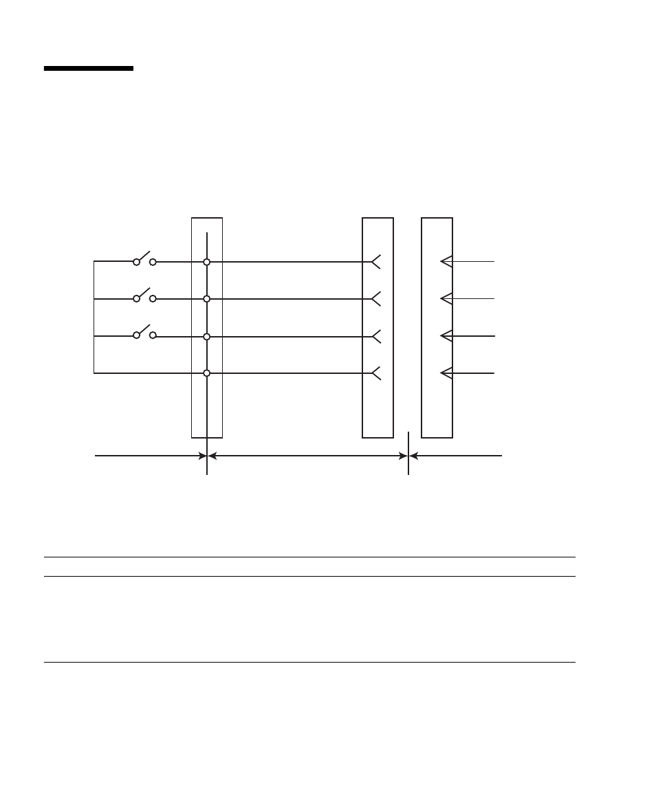
FIGURE E-1
shows the signal line configuration when connected to a UPS.
FIGURE E-1
Connection with UPS and the Server
TABLE E-1
defines these signal lines.
TABLE E-1
UPS Interface Signals
Signal name
Definitions
Pin number
Remarks
*BPS/*UALM
Signal indicates faulty UPS conditions
6
Normal: OFF
Failure: ON
*BTL
Signal provides a warning of a low battery level
and a pending UPS failure.
7
Normal: OFF
Warning: ON
(Note1)
*BTL
*BPS/*UALM
*ACOFF
SG
*BTL
*BPS/*UALM
*ACOFF
SG
UPS cable
UPS
Server
7
6
9
5
1