Measuring optical loss, Measuring output power – Fluke Series II User Manual
Page 60
Cable Tests
Test Fiber Optic Cable
4
4-11
Measuring Optical Loss
After setting the reference, do not disturb the source
connection as you make connections to measure optical
loss (Figure 4-9). If the fiber test is not already running,
press
(AutoTest) from the top level display to start
the test.
Measuring Output Power
Make the connections shown in Figure 4-10. If the fiber
test is not already running, press
(Autotest) from the
top-level display to start the test.
Output power, optical power loss, and the current
reference level are shown in microwatts (
µ
W) and
decibels (dBm or dB) (Figure 4-7). The power and loss
measurements are updated continuously. Table 4-1
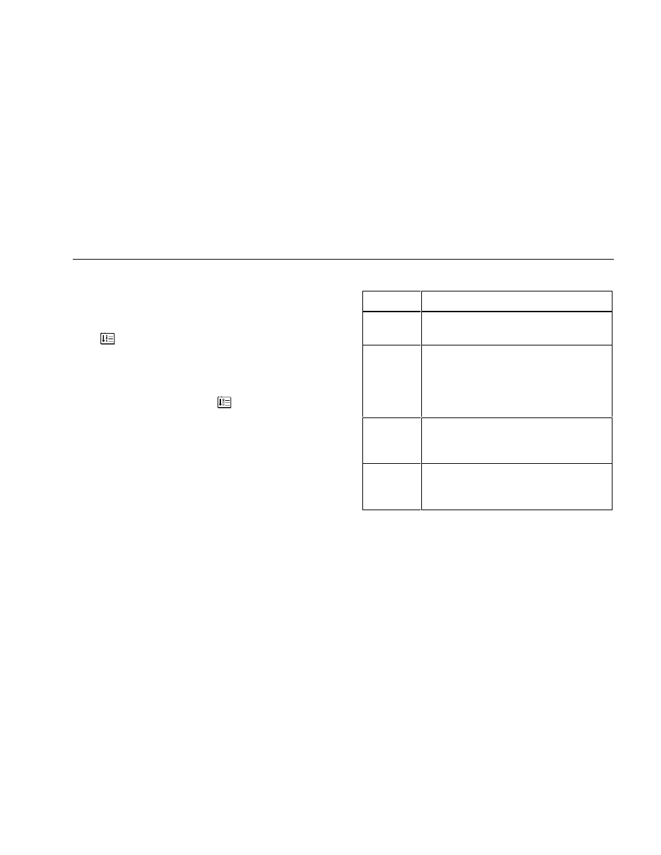
defines the terms used during the Fiber Test.
Table 4-1. Fiber Test Terminology
Term
Definition
Reference
Power measured on a known reference
cable.
Power
Measured power in milliwatts and dBm.
dBm is the ratio of the measured power to
one miliWatt. The formula the Network
Assistant uses for calculating dBm is:
Power (dBm) = 10 × log × Power (mW)
Loss
The amount of power loss on the
measured cable.
Loss = Reference - Measured Power
Loss Limit
Acceptable power loss. If the Loss is
greater than this value, the test reports
FAIL.
Otherwise, it reports
PASS.