Agp connector, 2 agp connector – HP D315 User Manual
Page 63
Technical Reference Guide
4.3.2 AGP CONNECTOR
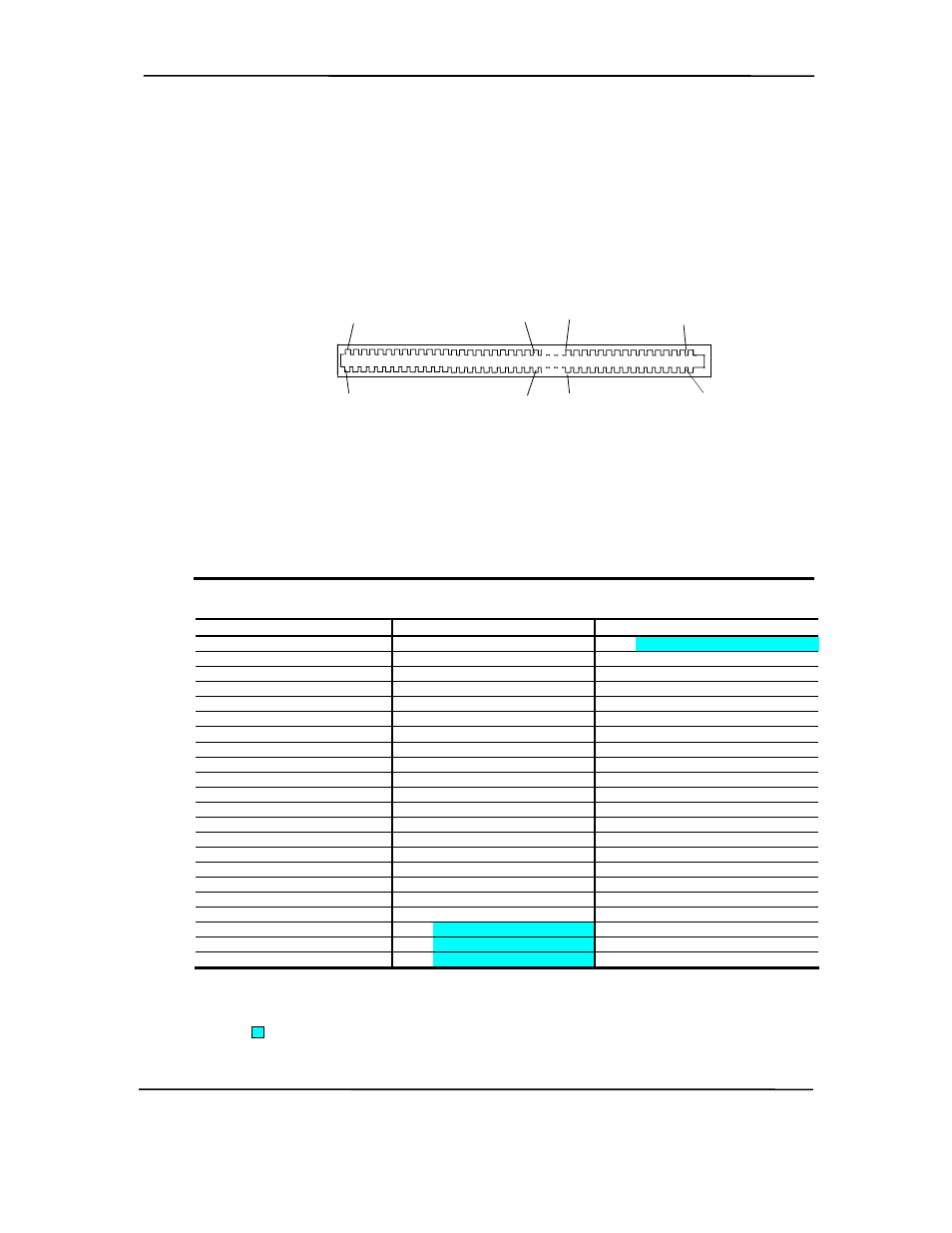
Figure 4-8 shows the system’s keyed AGP connector that accepts only 1.5-volt AGP adapters.
The pin out is listed in Table 4-4.
B94
A94
B46
B41
A46
A41
B1
A1
A66
B66
Figure 4-9. AGP Bus Connector
Table 4-4. AGP Bus Connector Pinout
Table 4-4.
AGP Bus Connector Pinout
Pin
A Signal
B Signal
Pin
A Signal
B Signal
Pin
A Signal
B Signal
01 +12
VDC OVRCNT-
23 GND
GND
45 VDD3
VDD3
02 Type
Det- VDD
24 NC
VDD3
Aux 46 TRDY- DEVSEL-
03 NC
VDD
25 VDD3
VDD3
47 STOP- VDDQ
04 USBN
USBP
26 PAD30 PAD31
48 PME-
PERR-
05 GND
GND
27 PAD28 PAD29
49 GND
GND
06 INTA-
INTB-
28 VDD3
VDD3
50 PAR
SERR-
07 RESET CLK
29 PAD26 PAD27
51 PAD15 CBE1-
08 GNT-
REQ-
30 PAD24 PAD25
52 VDDQ VDDQ
09 VDD3
VDD3
31 GND
GND
53 PAD13 PAD14
10 ST1
ST0
32 AD_STB1-
AD_STB1 54 PAD11 PAD12
11 NC
ST2
33 CBE3- PAD23
55 GND
GND
12 PIPE-
RBF-
34 VDDQ VDDQ
56 PAD09 PAD10
13 GND
GND
35 PAD22 PAD21
57 CBE0- PAD08
14 WBF-
NC
36 PAD20 PAD19
58 VDDQ VDDQ
15 SBA1
SBA0
37 GND
GND
59 AD_STB0-
AD_STB0
16 VDD3
VDD3
38 PAD18 PAD17
60 PAD06 PAD07
17 SBA3
SBA2
39 PAD16 CBE2-
61 GND
GND
18 SB_STB- SB_STB 40 VDDQ VDDQ
62 PAD04 PAD05
19 GND
GND
41 FRAME- IRDY-
63 PAD02 PAD03
20
SBA5 SBA4 42
NC
VDD3 Aux
64
VDDQ
VDDQ
21 SBA7
DBA6
43 GND
GND 65
PAD00
PAD01
22
NC NC 44
NC
NC 66
VREFGC
VREFCG
NOTES:
NC = Not connected
VDDQ = 3.3 VDC when TYPE DET- is left open by AGP 1X/2X card.
VDDQ = 1.5 VDC when TYPE DET- is grounded by AGP 4X card.
= Keyed spaces on 1.5-volt AGP connector.
Compaq D315 and hp d325 Personal Computers
Featuring the AMD Athlon XP Processor
Second Edition - April 2003
4-13