Installing electrical parts, X-motor & x-sensor (black marking), Y-motor & y-sensor (yellow marking) – XYZprinting Crazy3DPrint CZ-300 DIY 3D Printer User Manual
Page 13
11
4-2
Cable Tie (Min. *4)
Accessory Preparation
11
Control Box & Power Supply (*1)
C
D
A
B
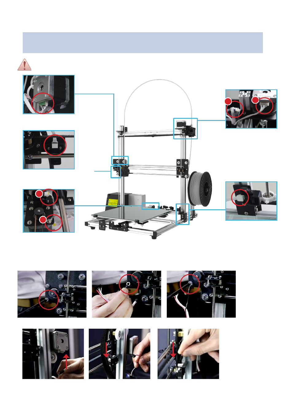
INSTALLING ELECTRICAL PARTS
Must Not
turning on the power supply during the assembly, it easily gets electric shock. For easy
identification, users may refer to the color marking for installation.
X Axis Motor
(6PIN Black Housing)
C: Extruder Motor
(6PIN Housing)
D: Z Axis Motor
(6PIN Housing)
X Axis Sensor
(3PIN Black Housing)
Z Axis Sensor
(3PIN White Housing)
A: Y Axis Motor
(6PIN Yellow Housing)
B: Y Axis Sensor
(3PIN Yellow Housing)
X-Motor & X-Sensor (Black Marking)
1) Remove the screw from the X-motor; following place the ground wire ring on the screw hole and tighten by the screw.
2) Plug the 6-pin black housing into the X-motor socket; following plug the 3-pin black housing into the X-sensor socket.
Y-Motor & Y-Sensor (Yellow Marking)
(Install the longer wire
onto the extruder motor)
(Install the shorter wire
onto the Z axis motor)