Quintum Technologies Tenor Call Relay SP User Manual
Page 23
P/N 480-0048-00-10
2-5
Chapter 2: Hardware Components
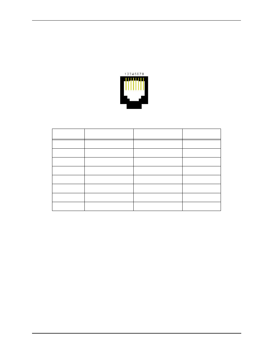
10/100 Base-T Ethernet ports. Four Ethernet ports; each port provides an RJ-45 jack for an individual con-
nection to a 10/100 Ethernet LAN switch or hub via RJ-45 cable. Each Ethernet port provides an RJ-45 jack
for an individual connection to a 10/100 Ethernet LAN switch or hub via RJ-45 cable. One port is functional;
the other three are for the future use. These three ports can be optionally purchased, when they are available.
Once functional, these ports can be configured with a unique IP and MAC address.
Figure 2-4 10/100 Ethernet Port Pin Order
Table 2-2 Input/Output 10/100 Ethernet port
Link LEDs. The CPU card contains four Link and associated TX/RX Status LEDs, viewable from the front
and rear of the chassis, to provide a high level indication of the system operational mode and chassis activity.
Each Link LED relates to one Ethernet line on the rear of the cards.
Pin #
Signal
Definition
Color
1
TX +
Transmit Data
White w/orange
2
TX -
Transmit Data
Orange
3
RX +
Receive Data
White w/green
4
RSVD
Reserved
Blue
5
RSVD
Reserved
White w/blue
6
RX -
Receive Data
Green
7
RSVD
Reserved
White w/Brown
8
RSVD
Reserved
Brown