Figure 8-8, l, He- 111 − corrective maintenance, Figure 8-8. control box and recessed panel – AERCO SWDW68 U-Tube Double-Wall Heaters w/ECS User Manual
Page 72
HE-
111 − CORRECTIVE MAINTENANCE
Rev B Mar 2013
8-18
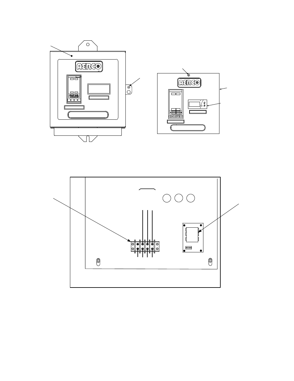
TEMP CONTROLLER
HOLD
RUN
AUTO
MAN
2408
PT.NO.
OVER TEMP SWITCH
PANEL
DOOR
CAPTIVE
SCREW
Figure 8-8. Control Box and Recessed Panel
2. Swing down the recessed panel and locate Terminal Block TB-2 (Figure 8-9).
REAR
TB-2
LINE
NEUTRAL
GROUND
100
101
102
GND
FRONT
VOLTAGE
REGULATOR
TERMINAL
BLOCK TB-2
EXTERNAL POWER WIRING
(120 VAC)
Figure 8-9. Control Box Interior Bottom View Showing Power Connections
3. Disconnect the Line, Neutral and Ground leads connected to Terminal Block TB-2.
4. Referring to figures in previous chapters (identified below), disconnect the Control Box cables from
the following devices:
a. Figure 1-3: Disconnect the Actuator cable (terminated in a 3-pin Molex connector) from the
Control Valve Actuator.
b. Figure 2-1. Disconnect the outlet temperature dual sensor cables (terminated in 4-pin Molex
connectors) from the DHW outlet dual temperature sensor installed in the upper head
TM
PT.NO.
SET
F
AUTO
RUN
MAN
HOLD
OP 1
OP 2
SP2
REM
2408
OVER TEMP SWITCH
TEMP CONTROLLER
PT.NO.
PANEL CAPTIVE
SCREW
OVER-
TEMPERATURE
SWITCH
RECESSED
PANEL