6 recirculation pump replacement, He- 111 − corrective maintenance, Caution – AERCO SWDW68 U-Tube Double-Wall Heaters w/ECS User Manual
Page 70
HE-
111 − CORRECTIVE MAINTENANCE
Rev B Mar 2013
8-16
CAUTION
Ensure that the replacement linkage assembly, adapter and scale are identical to those
removed in previous steps. Also, ensure that the linkage pin (Figure 8-6) is set to the
proper position for the Control Valve size. Failure to observe this precaution may
result in improper Control Valve operation.
65. Using a new gasket (29), position the replacement linkage assembly on the Valve top (21). Secure
the linkage assembly to the Valve top using the previously removed cap screws (29).
66. Install the indicator plate on the Valve shaft (16) with the curved end facing upward (Figure 8-4)
67. Attach the Valve shaft (16) to the linkage adapter by rotating the shaft counterclockwise (as viewed
from above). If the Valve shaft cannot be turned by hand, use an open-end wrench to turn the
“double-nuts” on the shaft until it engages the linkage adapter threads. Insert the shaft into the linkage
adapter until the hex nuts (17) are snug against the indicator plate.
68. Press down on the Valve shaft (16) to compress the pilot spring (10) in the Valve body.
69. With the pilot spring compressed, verify that the indicator plate is aligned with the “0” (zero) on the
scale (28). If necessary, rotate the Valve shaft until the plate is aligned with “0”.
70. Replace the Actuator using steps 50 through 57, above.
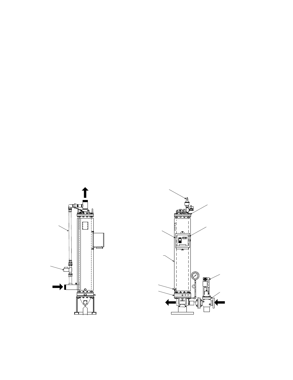
8.2.6 Recirculation Pump Replacement
The recirculation pump is required to assure proper heat exchanger operation and has an expected
service life of five years. The pump is installed in the recirculation piping (see Figure 8-7) to continuously
circulate domestic water through the heat exchanger, even when there is no DHW demand.
AERCO
STEAM INPUT
CONDENSATE OUTPUT
SHELL ENCLOSING THE
TUBE BUNDLE
COLD WATER
INPUT
HOT WATER OUTPUT
CONTROL BOX
RECIRCULATION
PIPING
RECIRULCATION
PUMP
TOP HEAD
BOTTOM HEAD
CXT-E CONTROL
VALVE
CXT-E ACTUATOR
PLUGGED DRAIN
POWER SWITCH
RELIEF VALVE
Figure 8-7. Recirculation Pump Mounted in Recirculation Piping
Use the following procedure to replace the recirculation pump:
1. Turn OFF both the external power circuit breaker to the DW-series heat exchanger and the power
switch on the side of the Control Box.
2. Close all stop valves in the Steam Input and Condensate Output lines.