3 electronic control system, 1 ecs block diagram, He– 111− functional description – AERCO SWDW68 U-Tube Double-Wall Heaters w/ECS User Manual
Page 24
HE–
111− FUNCTIONAL DESCRIPTION
Rev B Mar 2013
3-4
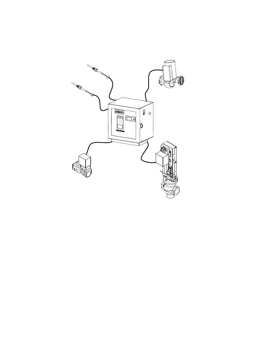
3.3 ELECTRONIC CONTROL SYSTEM
The Electronic Control System consists of the internal Control Box components and a number of sensor
and safety devices distributed throughout the heat exchanger assembly (see Figure 3-4).
DHW
DUAL OUTLET
TEMP. SENSOR
OVER-TEMPERATURE
SOLENOID VALVE
CONTROL BOX
ASSEMBLY
CONSTANT FLOW
RECIRCULATION
PUMP
FEED-FORWARD
MIXTURE TEMP.
SENSOR
CXT-E ACTUATOR
CXT-E CONTROL
VALVE
Figure 3-4. Electronic Control System Components
3.3.1 ECS Block Diagram
A simplified block diagram of the ECS is presented in Figure 3-5.
This manual is related to the following products: