5 linkage assembly replacement, He- 111 − corrective maintenance, Neptronic – AERCO SWDW68 U-Tube Double-Wall Heaters w/ECS User Manual
Page 68
HE-
111 − CORRECTIVE MAINTENANCE
Rev B Mar 2013
8-14
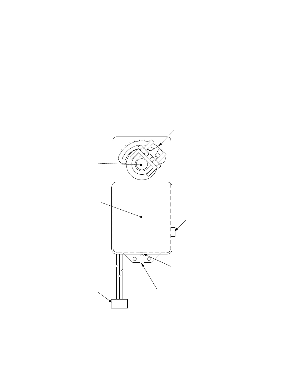
51. Slide the Actuator onto the linkage shaft.
52. Ensure that the pin on the linkage assembly is inserted in the center slot on the bottom of the
Actuator (Figure 8-5).
53. Verify that the indicator plate on the linkage assembly is aligned with “0” (zero) on the linkage scale.
Also, ensure that the Actuator dial is approximately at the 80° position.
54. Ensure that the pin on the linkage is inserted in the center slot on the Actuator.
55. Use an 8-mm wrench to tighten the hex nuts on the U-bolt to secure the Actuator to the shaft. Torque
the hex nuts to 60 inch-pounds.
56. Reconnect the Control Box cable to the Actuator.
57. When you have completed the Actuator replacement, perform the Control Valve adjustment
procedure in Section 4.2.
0
90
neptronic
1 2 3
COVER
SET SCREW
CLUTCH
PUSHBUTTON
DIAL &
POINTER
CENTER
SLOT
COVER
CABLE
CONNECTOR
LINKAGE
SHAFT
Figure 8-5. Actuator
8.2.5 Linkage Assembly Replacement
As illustrated in Figure 8-6, the linkage assembly part number will vary according to the valve size. The
CXT-E valve sizes ranging from 1.00 to 3.00 inches use linkage assembly Part No. 24038-1. The
4.00-inch CXT-E Valves use linkage assembly, Part No. 24038-2. The primary difference between the
24038-1 and 24038-2 linkage assemblies is the adapter shown in Figure 8-6. In addition, the linkage pin
location for the 24038-1 assembly is different for 1.00 to 2.00-inch valves and 2.50 to 3.00-inch valves.