Ac-105 instructions - ecs & cxt-e, Blinks valve size, Figure 4-2. actuator adjustment – AERCO SWDW68 U-Tube Double-Wall Heaters w/ECS User Manual
Page 30
AC-105 INSTRUCTIONS - ECS & CXT-E
4-2
Rev B Mar 2013
Automatically adjust the Actuator as follows:
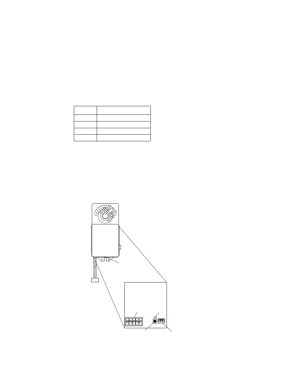
1. Referring to Figure 4-2, loosen the set screw on the Actuator cover.
2. Remove the Actuator cover to access the PC board containing the terminal connections,
DIP switches, Auto-Stroke (Reset) Button and LED.
3. Referring to Figure 4-1, use the power switch to turn on the Control Box and apply 24 VDC power to
the Actuator. (On the terminal strip: pin 2 = +24 VDC, pin 1 = Common).
The LED will light indicating that power is applied to the Control Box.
4. Wait approximately 10 seconds for the unit to perform its self-test. The LED will blink from one to four
times, depending on the size of the Valve, as follows:
Blinks
Valve Size
1
1”
2
1.25” and 2.5”
3
1.5” and 3”
4
2” and 4”
5. For full-stroke automatic adjustment, press the Reset button. The LED will light and the Actuator will
rotate in both directions to find its open and closed Valve position stops.
6. When the automatic adjustment is complete, the LED will blink from one to four times, depending on
the size of the valves, as described in step 4, above.
7. Turn the Control Box power off to disconnect power to the Actuator.
8. Replace the Actuator cover and tighten the set screw.
0
90
neptronic
1 2 3
1
2
3
4
5
1
2
3
DIP SWITCHES (3)
(ALL IN UP POSITION)
AUTO-STROKE
(RESET) BUTTON
LED
TERMINALS
PC BOARD
COVER
SET SCREW
ACTUATOR
Figure 4-2. Actuator Adjustment