3 making the piping connections, He- 111 − installation, Caution – AERCO SWDW68 U-Tube Double-Wall Heaters w/ECS User Manual
Page 15
HE-
111 − INSTALLATION
Rev B Mar 2013
2-5
2.3 MAKING THE PIPING CONNECTIONS
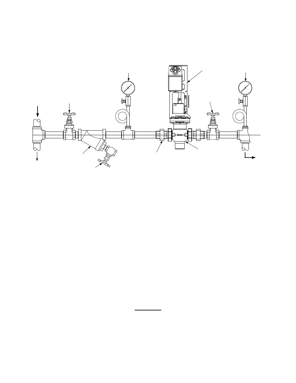
Figure 2-4 illustrates the recommended CXT-E Control Valve installation for steam flow.
TO HEATER
FROM
STEAM
SOURCE
UPSTREAM
SHUTOFF
VALVE
LOW SIDE
PRESSURE
GAUGE
CXT-E ACTUATOR
HIGH SIDE
PRESSURE
GAUGE
DOWNSTREAM
SHUTOFF VALVE
PIPE UNIONS (NOT
REQUIRED WHEN
VALVE IS FLANGED)
STRAINER
TO TRAP &
CONDENSATE
DRAIN
BLOW-OFF VALVE
NOTE:
KEEP PIPING AS SHORT
AS POSSIBLE)
CXT-E CONTROL
VALVE
Figure 2-4. Recommended Control Valve, CXT-E Installation for Steam Flow
1. Install the CXT-E Control Valve with the Actuator linkage in the vertical, upright position, as shown.
2. For maintenance purposes, install pipe unions with threaded ends to simplify removal from the steam
line.
3. Blow out all pipe lines to remove dirt chips, scale or other foreign matter which could adversely affect
Control Valve (“Valve”) operation when in service.
4. Install an in-line strainer upstream of the Valve (as illustrated on the left side of Figure 2-4) to protect
against foreign matter entering the Valve during service operation.
5. Ensure that the steam line is properly trapped to prevent accumulation of condensate ahead of the
Valve.
6. Install metal-seated, gate-type shutoff valves upstream and downstream of the Valve so that it can be
readily removed from the line for maintenance.
7. Install pressure gauges on both sides of the Control Valve, as shown in Figure 2-4.
8. The high-side pressure gauge is provided for adjustment and maintenance purposes. The low-side
pressure gauge is intended to ensure that the correct pressure is available to monitor the operation of
the temperature regulator valve. The low-side pressure gauge measures the pressure of the steam`.
CAUTION
When installing the Valve, DO NOT use the Actuator linkage frame at the top of the Valve
body for leverage. Use pipe wrenches on the inlet and outlet hex of the Valve body.
9. Install the Valve so that the arrow on the Valve body points in the direction of steam flow.
10. After the Valve has been installed in the steam or hot water line, ensure that all piping connections
are secure and leak-tight.