1 valve shaft seal retainer replacement, He- 111 − corrective maintenance – AERCO SWDW68 U-Tube Double-Wall Heaters w/ECS User Manual
Page 61
HE-
111 − CORRECTIVE MAINTENANCE
Rev B Mar 2013
8-7
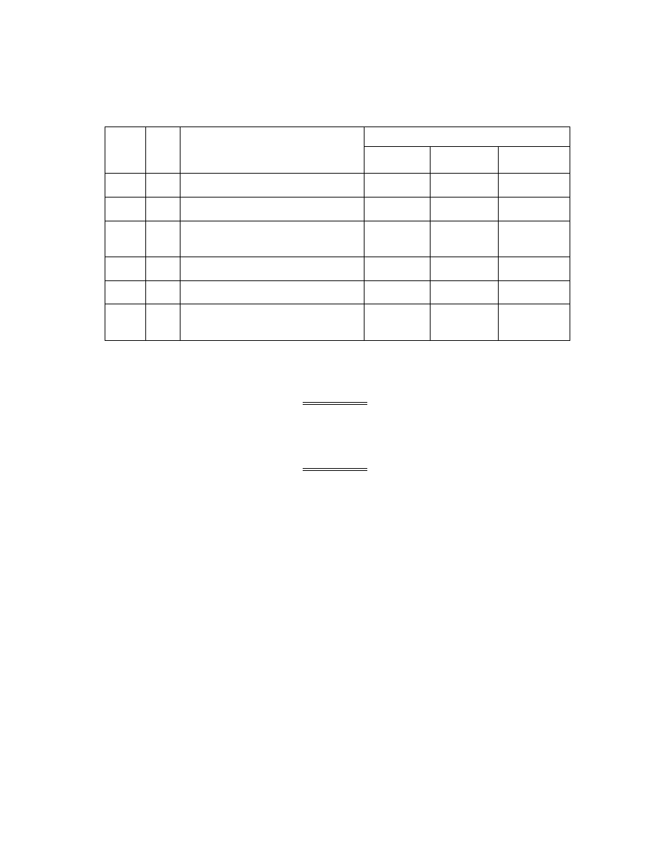
Table 8-2. PARTS LIST FOR VALVE ASSEMBLIES, TYPE CXT-E ( SIZES 2.50” TO 4.00”),
continued
VALVE SIZE AND PART NUMBERS
ITEM
QTY
PART NAME
2.50 INCH
3.00 INCH
4.00 INCH
26
1
LINKAGE
24038-1
24038-1
24038-2
27
1
ACTUATOR
69009
69009
69009
28
1
SCALE
59028-
2.50
59028-3
59028-4
29
1
GASKET
81046
81046
81046
30
2
HEX NUT, 8-32
123332
123322
123322
31
1
PILOT SPRING BACKUP
WASHER
N/A
N/A
122246
8.2.1 Valve Shaft Seal Retainer Replacement
WARNING
BEFORE PROCEEDING WITH THIS OPERATION, ENSURE THAT THE CONTROL
VALVE HAS BEEN ISOLATED FROM THE STEAM SUPPLY. LIVE STEAM CAN
CAUSE SERIOUS BURNS TO PERSONNEL.
WARNING
ENSURE THAT ELECTRICAL POWER TO THE ELECTRONIC CONTROL SYSTEM
AND ACTUATOR HAS BEEN DISCONNECTED. SERIOUS INJURY TO PERSONNEL
CAN RESULT IF THIS WARNING IS NOT OBSERVED.
To replace the valve shaft seal retainer proceed as follows:
1. Referring to Figure 8-1 or Figure 8-2, loosen the hex nuts (17) under the indicator plate approximately
one-half turn clockwise.
2. Disconnect the linkage adapter from the valve shaft (16) by turning the shaft clockwise (as viewed
from above). If the valve shaft cannot be turned by hand, use an open-end wrench to turn the
“double-nuts” on the shaft until it disengages the linkage adapter threads.
3. Remove the indicator plate from the Valve shaft (16).
4. Remove the two cap screws (19) securing the linkage assembly (26) to the Valve top (21).
5. With the Actuator assembly (27) still attached, remove the complete linkage assembly (26) from the
valve top. Also, remove the gasket (29).
6. If the packing nut (18) is leaking or binding the Valve shaft, replace it.
7. Measure and record the current position of the hex nuts (17) from the end of the Valve shaft (16).
This will simplify adjustment of the Actuator linkage during reassembly.
8. Completely remove the hex nuts (17) from the Valve shaft (16).
9. Remove the packing nut (18) and the packing assembly (20) from the Valve body.