2 double-wall heat transfer and water leakage, 3 principal mechanical components, He– 111− functional description – AERCO SWDW68 U-Tube Double-Wall Heaters w/ECS User Manual
Page 22
HE–
111− FUNCTIONAL DESCRIPTION
Rev B Mar 2013
3-2
the delivered hot water to within ±4°F of the Control Box setting, under normal, diversified load conditions
(load fluctuations of up to 25% of water heater capacity).
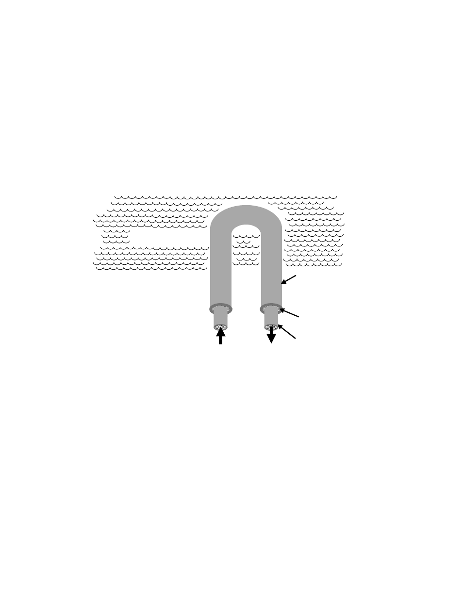
3.2.2 Double-Wall Heat Transfer and Water Leakage
As illustrated in Figure 3-2, the heat exchanger’s primary tubes incorporate double-wall construction in
which the inner and outer tube walls are separated by air space. The steam flows within the double-wall
primary tubes’ inner walls. Any condensate leaking outward through the inner walls is trapped within
vented air space between the inner and outer tube walls. Any service water that leaks inward through the
outer tube walls is similarly contained within the air space. The accumulated leakage water is conducted
along these air spaces, collected in the bottom head (see 3.2.3.2) and discharged through an
atmospherically vented leak detection port. This construction effectively provides double protection
against primary steam or condensate leaking into the service water, or vice versa. However, it is not
unusual for moisture to appear at the leak detection port at initial heat exchanger start-up, even when
there are no tube leaks. This moisture results from water condensing during the manufacturing process
and being expelled when the system is initially operated.
STEAM
PRIMARY TUBE
INNER WALL
HEATED SHELL-SIDE
SERVICE WATER
PRIMARY TUBE
OUTER WALL
AIR SPACE
Figure 3-2. Segment of a Double-Wall Primary Tube
3.2.3 Principal Mechanical Components
The AERCO DW-series heat exchanger consists of the following principal mechanical components (see
Figure 3-3):
• Shell and heads (3.2.3.1)
• Double-wall U-bend tube bundle and tubesheet (3.2.3.2)
• Recirculation pipe and pump (3.2.3.3)
• Electronic CXT-E Control Valve (3.2.3.4)