4 actuator replacement, He- 111 − corrective maintenance – AERCO SWDW68 U-Tube Double-Wall Heaters w/ECS User Manual
Page 67
HE-
111 − CORRECTIVE MAINTENANCE
Rev B Mar 2013
8-13
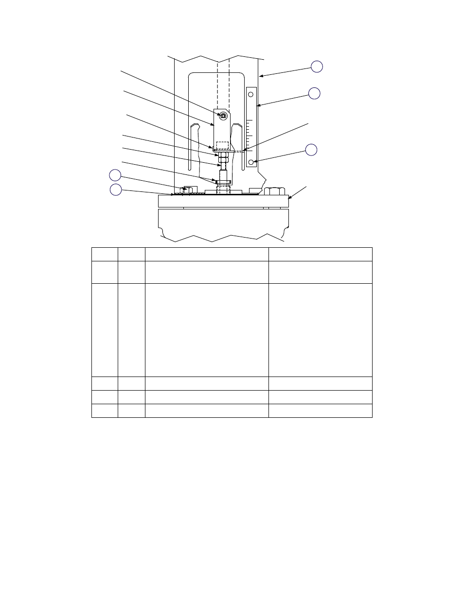
SHAFT PIN
LOCATION
LINKAGE ADAPTER
INDICATOR
PLATE
0
1
LINKAGE
ASSEMBLY
SCALE
PACKING NUT
VALVE TOP
LINKAGE
GASKET
HEX NUTS (2)
VALVE SHAFT
VALVE BODY
5
CAP SCREW
8-32 HEX NUT
(FAR SIDE)
4
INDICATOR PLATE
(CURVED END)
3
2
1
ITEM
QTY
PART DESCRIPTION
PART NUMBER
1
1
LINKAGE ASSEMBLY
24038-1 (1” TO 3” VALVES)
24038-2 (4” Valve)
2
1
SCALE
59028-1 (1” VALVE)
59028-1.25 (1.25” VALVE)
59028-1.5 (1.5” VALVE)
59028-2 (2” VALVE)
59028-2.5 (2.5” VALVE)
59028-3 ( 3” VALVE)
59028-4 (4” VALVE)
3
2
HEX NUT, 8-32
123322
4
2
CAP SCREW, 3/8-16 x 5/8 LONG
54014
5
1
LINKAGE GASKET
81046
Figure 8-4. linkage Assembly Installation Details
8.2.4 Actuator Replacement
The Actuator includes no repairable parts. Therefore, if the troubleshooting procedures point to the
Actuator as the cause of the fault, replace it as described in the following steps:
46. Disconnect and lock-out/tag-out the AC power supplied to the Control Box. Use a voltmeter to ensure
that all voltages are zero before continuing.
47. Disconnect the Control Box cable connected to the Actuator.
48. Use an 8-mm wrench to loosen the hex nuts securing the Actuator to the linkage shaft.
49. Completely remove the defective Actuator from the shaft.
50. To install a replacement Actuator, depress and hold the clutch button (see Figure 8-5) and rotate the
pointer to approximately 80° on the dial. Release the clutch.