2 connecting ac power to the control box, 3 wiring the cxt-e actuator, He- 111 − installation – AERCO SWDW68 U-Tube Double-Wall Heaters w/ECS User Manual
Page 18: Tm pt.no, Pt.no
HE-
111 − INSTALLATION
Rev B Mar 2013
2-8
TM
PT.NO.
SET
F
AUTO
RUN
MAN
HOLD
OP 1
OP 2
SP2
REM
2408
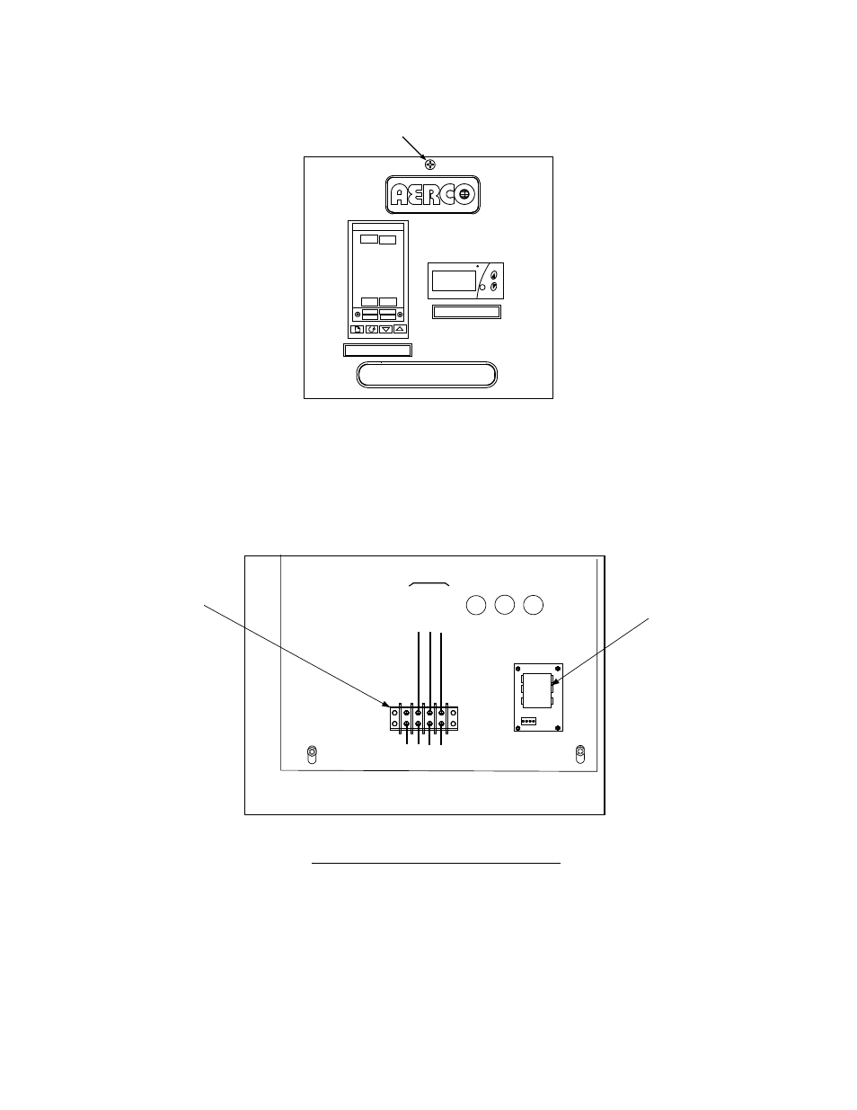
OVER TEMP SWITCH
TEMP CONTROLLER
PT.NO.
PANEL CAPTIVE
SCREW
Figure 2-6. Recessed Panel Behind Control Box Door
2.4.2 Connecting AC Power to the Control Box
3. Feed the external 120 VAC power leads through the cutout labeled “POWER IN” on the right side of
the Control Box.
4. Connect the LINE, NEUTRAL and GROUND leads to the TB-2 terminals shown in Figure 2-7.
CONTROL BOX - INTERIOR BOTTOM VIEW
REAR
TB-2
L
IN
E
N
E
U
T
R
A
L
G
R
O
U
N
D
1
0
0
1
0
1
1
0
2
G
N
D
FRONT
VOLTAGE
REGULATOR
TERMINAL
BLOCK TB-2
EXTERNAL POWER WIRING
(120 VAC)
Figure 2-7. ECS Control Box AC Power Connections
2.4.3 Wiring the CXT-E Actuator
5. Connect the Control Box cable labeled ACTUATOR to the 3-pin connector plug on the CXT-E
Actuator.