Operation, Vacuum system – Prochem Legend XL User Manual
Page 20
OPERATION
86037400 02/16/07
3-10
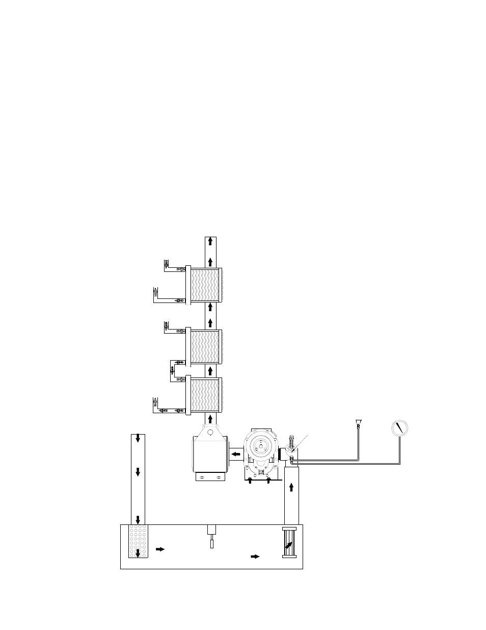
VACUUM
GAUGE
LUBRICATION
CUP
VACUUM
BLOWER
VACUUM
SILENCER
VACUUM
RELIEF
VALVE
FROM PRESSURE
REGULATOR
VACUUM EXHAUST
"RADIATOR TYPE"
STAINLESS STEEL
HEAT EXCHANGER
TO
SOLUTION OUTLET
TO WATER BOX
LEVEL SENSOR
(ENGINE SHUT-OFF SWITCH)
FILTERS
VACUUM EXHAUST
OUTLET
VACUUM EXHAUST
"RADIATOR TYPE"
COPPER
HEAT EXCHANGER
VACUUM EXHAUST
"RADIATOR TYPE"
STAINLESS STEEL
HEAT EXCHANGER
VACUUM
INLET
STRAINER
FROM PRESSURE
REGULATOR
WASTE TANK
VACUUM SYSTEM
The engine turning an air pump generates vacuum.
The air is channeled in one side of the vacuum
pump, compressed and discharged on the opposite
side, creating airflow.
The movement of air is used to do the work
necessary for the extraction process. A vacuum
nozzle applied to the carpet surface removes
moisture, dirt and spent chemicals. These elements
are conveyed back to a separating tank utilizing
hoses and the force of air. Particles of moisture and
dirt are separated in the vacuum tank using a series
of changes in direction and velocity. The air is then
filtered and rushes into the vacuum pump.
The vacuum pump compresses and heats the
incoming air. The hot discharged air is forced down
stream into a silencer for noise abatement. After
exiting the silencer, this hot air is mixed with the hot
air and gases from the engine. This mixture of hot
air and gases are then forced through 3 radiators
serving as heat collectors. Heat from the engine
and vacuum pump is then transferred into the
plumbing system raising the water temperature for
better cleaning.
The engine and blower speeds are factory set to
maximize vacuum pressure and provide sustained
system life. Do not alter the engine or vacuum
speeds outside the recommended ranges shown in
the Technical Specifications section.