INOR PROFIPAQ-L User Manual
Page 12
12
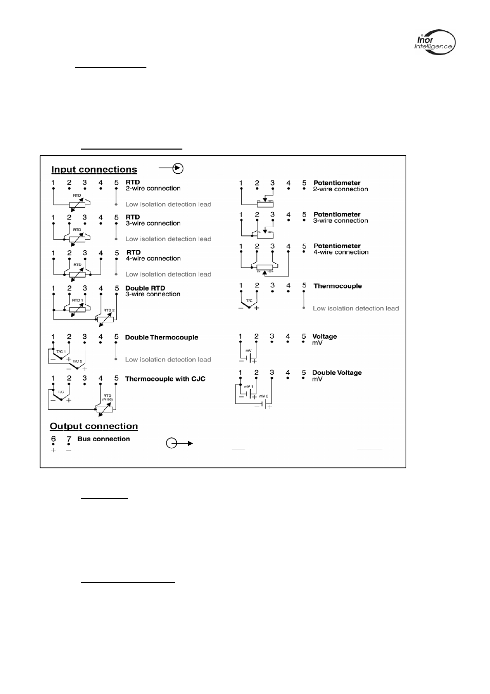
2.6 Connections
The input and output/power supply of the ProfIPAQ are connected according to
connection chart, Figure 12. The output connection (Bus connection) is polarity
independent. Also see Appendix B, Profibus cabling.
To ensure an adequate sensor connection, anchor the sensor lead wires beneath the flat
washer on the terminal screw.
2.6.1 Connection Diagram
Figure 12 Connection chart
2.6.2 LCD-W12
A special LCD-indicator, INOR LCD-W12, can be connected to the communication port of
the ProfIPAQ. It gets its power and digital data from the ProfIPAQ. The activation of the
communication port as a display connection and number of decimals to be shown in the
display are selected via the ProfiSoft software, see chapter 4. The display LCD-W12 is not
approved for mounting into Ex Hazardous area.
2.6.3 Ex Bus connection:
The models ProfIPAQ-HX and ProfIPAQ-HX/Dxy must be electrically connected via a
certified intrinsic safe power supply unit or an intrinsic safe segment coupler, which is
mounted outside the hazardous area, for use in Ex ia or Ex ib applications. For non-
incendive Ex nL applications (ProfIPAQ-H and ProfIPAQ-H/Dxy) the transmitter must be
connected to a standard power supply (Class 2 for USA). Provisions shall be made to protect
the transmitter from transient disturbances of more than 42V on power supply lines.