8 bottom panel connectors, 1 lan connection, 2 serial device connection – IEI Integration ACT-457A User Manual
Page 33: Ottom, Anel, Onnectors, Figure 2-14: lan connection
ACT-457A Panel PC
Page 25
PC.
S
te
p
0
:
2.8 Bottom Panel Connectors
Before operating the ACT-457A, connect the peripheral devices listed below.
2.8.1 LAN Connection
There are two external RJ-45 LAN connectors. The RJ-45 connectors enable connection
to an external network. To connect a LAN cable with an RJ-45 connector, please follow
the instructions below.
Step 1:
Locate the RJ-45 connectors on the bottom panel of the ACT-457A.
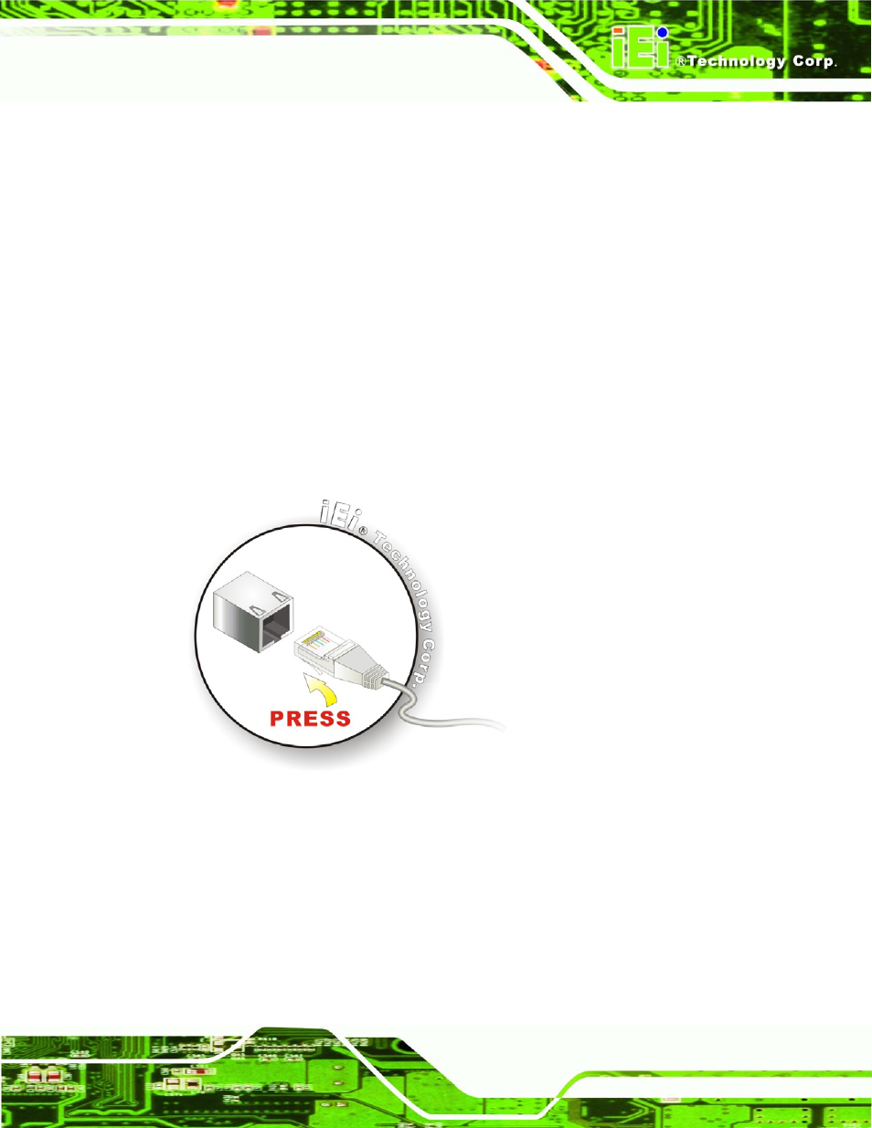
Step 2:
Align the connectors. Align the RJ-45 connector on the LAN cable with one of
the RJ-45 connectors on the bottom panel of the ACT-457A. See Figure 2-14.
Figure 2-14: LAN Connection
Step 3:
Insert the LAN cable RJ-45 connector. Once aligned, gently insert the LAN
cable RJ-45 connector into the onboard RJ-45 connector.
Step 0:
2.8.2 Serial Device Connection
The ACT-457A has two male DB-9 connectors on the bottom panel for serial devices to be
connected. Follow the steps below to connect a serial device to the ACT-457A POS
system.